Visual direction judgment adjustment mechanism

An adjustment mechanism and visual technology, which is applied in the assembly/disassembly of contact parts and the manufacture of wiring harnesses, etc., can solve the problems of unstable quality of sockets, large number of products, and high work intensity of sockets, etc.

Pending Publication Date: 2018-01-19
HEBI HAICHANG SPECIAL EQUIP
View PDF7 Cites 0 Cited by
  • Summary
  • Abstract
  • Description
  • Claims
  • Application Information

AI Technical Summary

Problems solved by technology

[0003] The present invention aims to solve the technical problems that there are a large number of products in the existing wire spigot, the work strength of the spigot is high, and the quality of the spigot is unstable, so as to provide a CCD to automatically determine the angle between the terminal crimping surface and the horizontal plane and automatically Visual direction adjustment mechanism for adjustment

Method used


Image

  • Visual direction judgment adjustment mechanism
  • Visual direction judgment adjustment mechanism
  • Visual direction judgment adjustment mechanism

Examples


Embodiment Construction

[0018] The following will clearly and completely describe the technical solutions in the embodiments of the present invention with reference to the accompanying drawings in the embodiments of the present invention. Obviously, the described embodiments are only some, not all, embodiments of the present invention. Based on the embodiments of the present invention, all other embodiments obtained by persons of ordinary skill in the art without making creative efforts belong to the protection scope of the present invention.

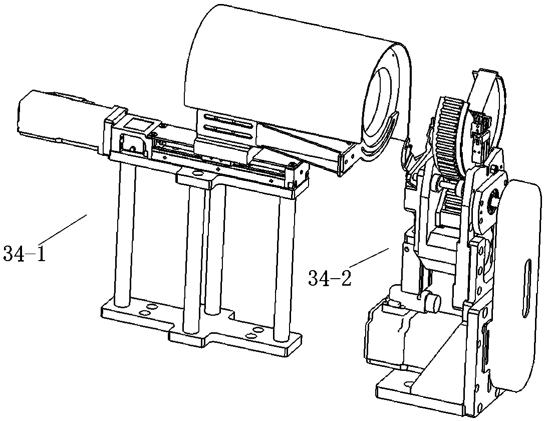
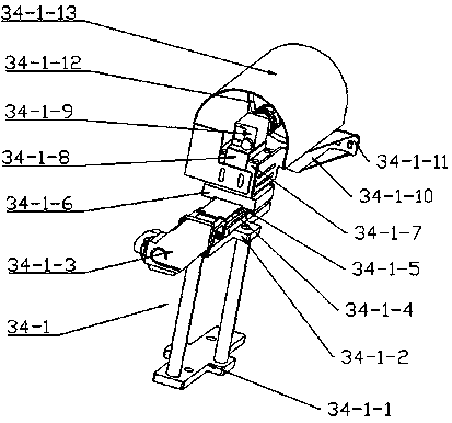
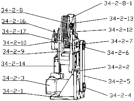
[0019] Such as Figure 1-4 As shown, a visual direction adjustment mechanism includes a relatively installed direction judgment vision module 34-1 and a rotation module 34-2. The rotation module 34-2 is installed in front of the direction judgment vision module 34-1, and the rotation module 34- The dial 34-2-16 of the rotary dial assembly in 2 corresponds to the camera 34-1-9 of the judgment vision module 34-1.

[0020] Specifically, the direction judgment vi...


PUM


Abstract

The invention discloses a visual direction judgment adjustment mechanism. The visual direction judgment adjustment mechanism comprises a direction judgment visual module and a rotation module mountedoppositely; the rotation module is mounted in front of the direction judgment visual module; and a shifting block of a rotation shifting block module in the rotation module is corresponding to a camera of the direction judgment visual module. A rotary motor drives a rotation pinion to rotate, and the rotation pinion drives a rotation rack wheel meshed therewith to rotate, and a rotation clamping claw fixed in the rotation centre of the rotation rack wheel tightly clamps a wring harness to rotate alongwith, so as to adjust an angle; the rotation shifting block assembly is mainly used for preventing droop of a terminal due to overlong extension to affect CCD imaging precision and quality. By virtue of the visual direction judgment adjustment mechanism, functions of camera shooting directionjudgment and dynamic adjustment of various kinds of terminals can be realized.

Description

technical field [0001] The invention belongs to the technical field of plug-in auxiliary equipment for wires in the wire harness industry, and specifically relates to a visual direction adjustment mechanism that can use a CCD to judge the angle between a crimped surface and a horizontal plane after crimping various wires and automatically adjust it to be parallel to the horizontal plane. Background technique [0002] At present, the domestic wiring harness enterprises are first to make the wire harness required for the plug-in sheath off-line, and transfer it from the logistics to the streamline area to complete the plug-in end manually, resulting in a large number of products in progress, high labor intensity for the plug-in workers, and unstable quality. An automatic equipment that can complete off-line, stripping, bolting, crimping, and inserting into the plastic sheath on one piece of equipment. Contents of the invention [0003] What the present invention aims to solv...

Claims


Application Information

Patent Timeline
IPC IPC(8): H01R43/20H01B13/012
Inventor 张海洋崔炳艺程朝锋李德阳李振涛申振生
Owner HEBI HAICHANG SPECIAL EQUIP
Why Eureka
Try Eureka