
LED display suite

A technology of LED display screen and LED lamp, which is applied in the direction of instruments, identification devices, etc., can solve the problems of large quantity of screws and nuts, inconvenient operation, high cost, etc., and achieve the effect of reducing labor intensity, saving cost, and simple and convenient operation

Active Publication Date: 2018-01-16
安徽锐新新能源科技有限公司
View PDF5 Cites 1 Cited by
  • Summary
  • Abstract
  • Description
  • Claims
  • Application Information

AI Technical Summary

Problems solved by technology

[0003] There is an existing LED display kit, which includes an LED cover and a bottom shell. The LED light cover is evenly distributed with through holes for installing LED lights. The bottom shell is a square outer frame, and the square outer frame is also provided with There is a longitudinal bracket, a plurality of mounting screw holes are symmetrically distributed on the bottom shell, and mounting holes are provided on the position of the LED cover corresponding to the mounting screw holes of the bottom shell, and the LED cover passes through the mounting holes and the bottom The mounting screw holes on the shell are fixed on the bottom shell by screws. The LED cover and the bottom shell are also provided with a plurality of screw holes corresponding to each other. The LED display kit passes through the LED cover and the bottom shell. The screw through holes on the bottom shell, utilize screws and nuts to fix it on the frame that is installed on the wall in advance for hanging the LED display kit on the wall; the structure of the LED display kit is simple, but the LED The display kit is fixed on the frame by the cooperation of multiple screws and nuts. During the installation or removal process, the screws and nuts need to be installed or removed one by one, which is very inconvenient to operate, especially when the size of the LED display is large. Using multiple LED display kits to splice LED pixel modules composed of LED lights requires a large amount of screws and nuts, and the cost is high, and it also increases the workload of installation and maintenance personnel, increasing the installation and maintenance personnel labor intensity

Method used


Image

  • LED display suite
  • LED display suite
  • LED display suite

Examples


Embodiment Construction

[0020] The present invention will be further described in conjunction with the accompanying drawings and specific embodiments.

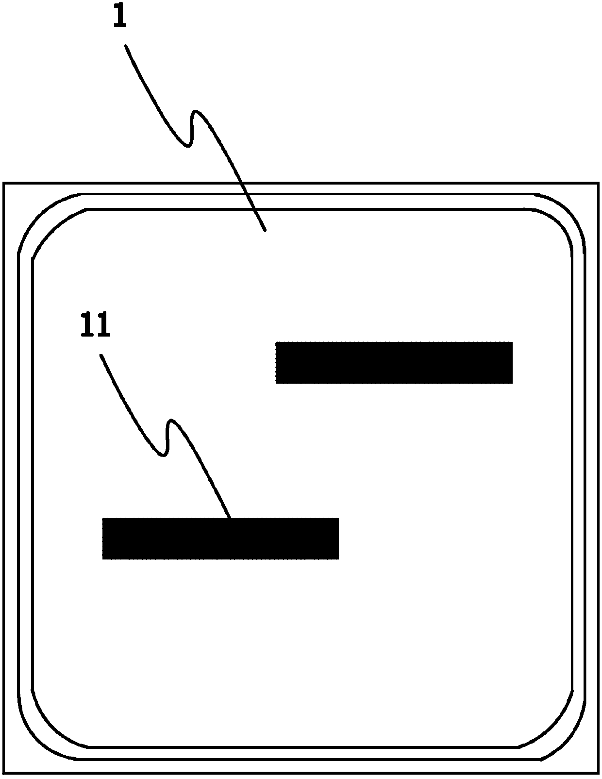
[0021] refer to Figure 1 to Figure 5 , the embodiment of the present invention discloses an LED display kit, comprising a bottom case 1, an LED cover with mounting holes for LED lamps uniformly distributed on the surface of the bottom case, and a fixing frame 2 for fixing and installing the bottom case , the bottom shell 1 is arranged with locking shafts 11 arranged in sequence along the height direction, the locking shafts 11 are provided with shaft holes along the axial direction, and the adjacent locking shafts 11 are arranged in a dislocation distribution;

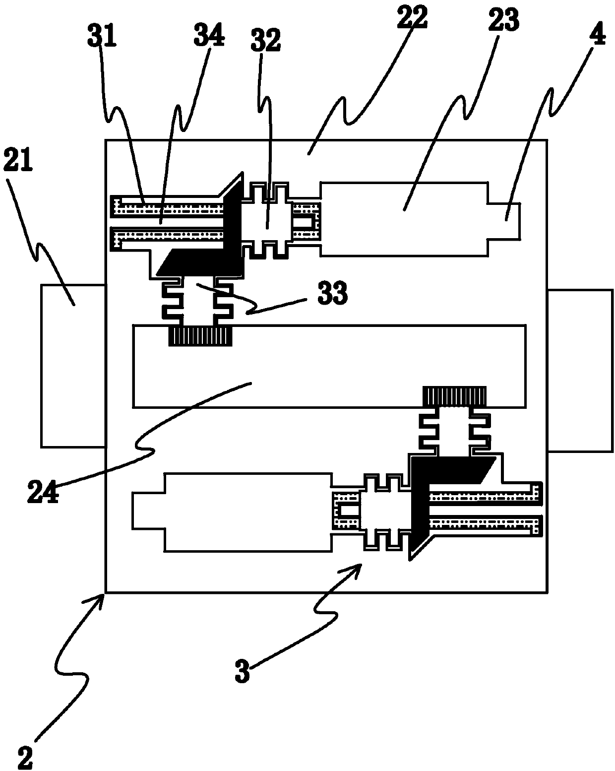
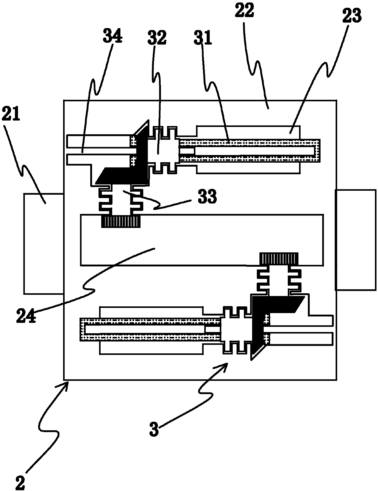
[0022] The fixed frame 2 includes a fixed base 21, the fixed base 21 is provided with a fixed bracket 22, the fixed bracket 22 is adapted to the shape of the bottom shell, and the fixed bracket 22 is provided with a locking shaft embedded The locking shaft holes 23; the fixed bracket 22 is ...


PUM


Abstract

The invention relates to the technical field of LED display, and provides an LED display suite which is convenient to disassemble, and capable of reducing costs and labor intensity of installation maintenance personnel. The LED display suite includes a base shell, an LED face cover with LED lamp mounting holes formed uniformly in the surface of the base shell, and a fixing frame for fixing and installing the base shell, a locking shaft is arranged on the base shell, a locking shaft hole for embedding the locking shaft is formed in the fixing frame, a locking part is arranged also on the fixingframe, the locking part comprises a threaded shaft, a transferring head and a rotating head, the expansion of the threaded shaft in the axial direction of the locking shaft hole is achieved through the rotating drive of the transferring head and the rotating head, and the detachable wear of the locking shaft by the threaded shaft is achieved.

Description

technical field [0001] The invention relates to the technical field of LED display, in particular to an LED display kit. Background technique [0002] With the continuous development of LED technology, LED display screens are widely used in various occasions such as indoors and outdoors. LED display screens use LED display kits to assemble and arrange LED pixel modules composed of LED lights into a matrix according to actual needs. It is a display screen fixed on the frame and composed of a display drive circuit, a DC power supply and software, etc., and with the changeable occasions where the LED display screen is applied and the improvement of requirements, how can the LED display screen be used? Easy and quick installation and removal of kits is a major issue in LED display applications. [0003] There is an existing LED display kit, which includes an LED cover and a bottom shell. The LED light cover is evenly distributed with through holes for installing LED lights. The...

Claims


Application Information

Patent Timeline
Patent Type & Authority Applications(China)
IPC IPC(8): G09F9/33
Inventor 庄黎玲
Owner 安徽锐新新能源科技有限公司
Learn More