
Optical cable wiring trough capable of feeding and turning optical cable flexibly

A technology for wiring troughs and optical cables, applied in the field of wiring troughs, can solve problems such as inconvenience, and achieve the effect of flexible and convenient use and simple operation.

Inactive Publication Date: 2018-01-16
HENAN HONGJUN COMM ENG CO LTD
View PDF8 Cites 1 Cited by
  • Summary
  • Abstract
  • Description
  • Claims
  • Application Information

AI Technical Summary

Problems solved by technology

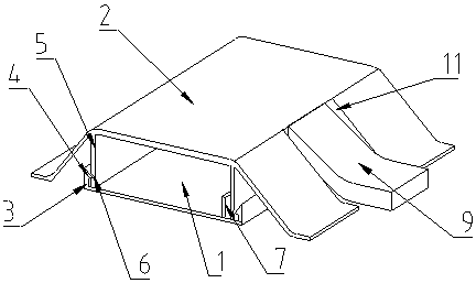
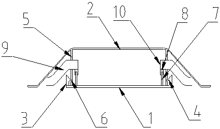
[0002] With the continuous development of FTTH, fiber-to-the-home and fiber-to-the-table have become a trend. In some cases, it is necessary to arrange open wires to the use area, which needs to be sent to the cable trough to protect the optical cables. Most of the wire slots are linear, and it is inconvenient when the wires need to be turned when they are used. Therefore, in order to solve the above problems, it is necessary to develop a wire slot for optical cables that can be flexibly redirected.

Method used


Image

  • Optical cable wiring trough capable of feeding and turning optical cable flexibly
  • Optical cable wiring trough capable of feeding and turning optical cable flexibly

Examples


Embodiment Construction

[0011] The technical solutions of the present invention will be further specifically described below through embodiments and in conjunction with the accompanying drawings.

[0012] Such as figure 1 , figure 2 As shown, a wiring trough for optical cables that can be flexibly turned around includes a base 1, a cover plate 2, a side plate 3, a convex buckle 4, a vertical plate 5, a buckle groove 6, a fixing plate 7, a connecting plate 8, and a connecting channel. Groove 9, diversion opening 10 and notch 11.

[0013] Wherein, the longitudinal section of the base 1 is roughly U-shaped, and side plates 3 are fixedly arranged on both sides of the base 1. Preferably, the base 1 and the side plates 3 are of an integrated structure, which is more durable and durable. The inner side is provided with a convex buckle 4, and the convex buckle 4 is an inverted triangle structure. The convex buckle 4 and the side plate 3 are also set as an integrated structure, which is more durable. The t...


PUM


Abstract

The invention discloses an optical cable wiring trough capable of feeding and turning an optical cable flexibly. The optical cable wiring trough comprises a base, a cover plate, side plates, convex buckles, vertical plates, buckle grooves, fixing plates, connecting plates, connecting through grooves, turning holes and notches, wherein the longitudinal cross section of the base takes the shape of aU generally; the side plates are arranged on two sides of the base; the convex buckles are arranged on the inner sides of the side plates; the top surface of the longitudinal cross section of the cover plate is a plane and is also of an arc-shaped structure generally; the vertical plates are fixedly arranged on two sides below the top surface of the cover plate; the buckle grooves corresponding to the convex buckles are formed in outer side surfaces of the vertical plates; fixing plates are also fixedly arranged on the inner sides of the side plates on the base; the connecting plates are connected with the fixing plates in a sliding manner; the connecting through grooves are fixedly formed in the top ends of the connecting plates; two ends of the connecting through grooves are opened; oneend of each connecting through groove is opened and is communicated with the space inside the base to form the turning holes; notches corresponding to the connecting through grooves are formed in theside surfaces of the cover plate. In a word, the optical cable wiring trough has the advantages of turning ability, flexible and convenient use and simple operation.

Description

technical field [0001] The invention relates to a wiring trough, in particular to a wiring trough for an optical cable that can be flexibly turned around. Background technique [0002] With the continuous development of FTTH, fiber-to-the-home and fiber-to-the-table have become a trend. In some cases, it is necessary to arrange open wires to the use area, which needs to be sent to the cable trough to protect the optical cables. Most of the wire slots are linear, and it is inconvenient to meet the situation that the wires need to be turned during use. Therefore, in order to solve the above problems, it is necessary to develop a wire slot for optical cables that can be flexibly redirected. Contents of the invention [0003] The object of the present invention is to overcome the deficiencies of the prior art, and provide a cable duct for optical cables that can be steered, flexible and convenient to use, and simple to operate. [0004] The object of the present invention is ...

Claims


Application Information

Patent Timeline
IPC IPC(8): G02B6/46
Inventor 李保杰
Owner HENAN HONGJUN COMM ENG CO LTD
Learn More