
A casing for a compressor

A compressor and shell technology, applied in the field of compressors, can solve problems such as the unsatisfactory shock absorption effect of the compressor, and achieve the effect of solving the poor sound insulation function

Active Publication Date: 2019-01-29
DONGYING HEBANG CHEM CO LTD
View PDF6 Cites 0 Cited by
  • Summary
  • Abstract
  • Description
  • Claims
  • Application Information

AI Technical Summary

Problems solved by technology

[0004] The purpose of the present invention is to provide a shell used on a compressor, which has the advantages of shock absorption and easy installation, and solves the problem of unsatisfactory shock absorption effect of the compressor

Method used


Image

  • A casing for a compressor
  • A casing for a compressor
  • A casing for a compressor

Examples


Embodiment Construction

[0021] The following will clearly and completely describe the technical solutions in the embodiments of the present invention with reference to the accompanying drawings in the embodiments of the present invention. Obviously, the described embodiments are only some, not all, embodiments of the present invention. Based on the embodiments of the present invention, all other embodiments obtained by persons of ordinary skill in the art without making creative efforts belong to the protection scope of the present invention.

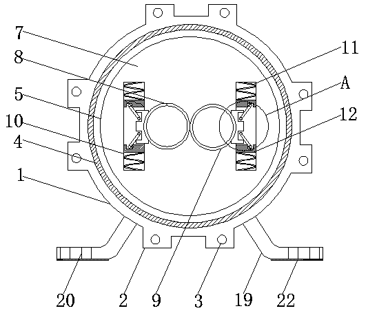
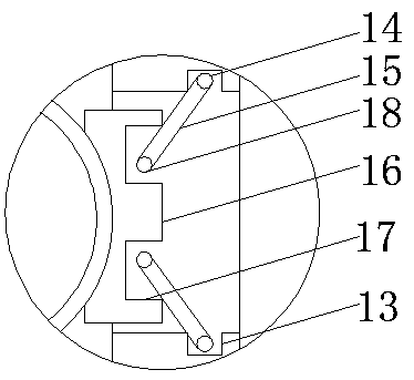
[0022] see Figure 1-4 , the present invention provides a technical solution: a shell used on a compressor, including a shell 1, both sides of the bottom of the shell 1 are fixedly connected with supporting legs 19, the supporting legs 19 are L-shaped legs, and the supporting legs 19 The bottom is fixedly connected with an anti-slip mat 22, which is in contact with the surface of the machine equipment. When the housing 1 is fixed, the air between the anti-slip...


PUM


Abstract

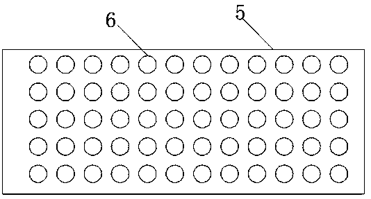
The invention discloses a shell used on a compressor. The shell comprises a shell body, wherein silencing holes are formed in equal distances are formed in the inner wall of a connecting cylinder; a baffle plate is fixedly connected with the back side of the shell; buffer grooves are formed in both sides of the front side of the baffle plate; springs are fixedly connected with the tops and the bottoms of the inner sides of the buffer grooves; buffer blocks are fixedly connected with one sides far away from the inner walls of the buffer grooves, of the springs; grooves are formed in one sides far away from the springs, of the buffer blocks; connecting rods are connected with the inner sides of the grooves in a penetration manner; chutes are formed in the tops and the bottoms of one sides close to the buffer grooves, of damping blocks; rotating shafts are connected with the inner sides of the chutes in the penetration manner. Due to matched use of the springs, the buffer blocks, the connecting rods, telescopic rods, the damping blocks and the rotating shafts, the problem that a compressor is poor in damping effect is solved, and due to matched use of the shell body, a rubber pad, theconnecting cylinder and the silencing holes, the problem that the compressor is poor in construction silencing function is solved.

Description

technical field [0001] The invention relates to the technical field of compressors, in particular to a shell used for compressors. Background technique [0002] The compressor is a driven fluid machine that raises low-pressure gas to high-pressure gas. It is the heart of the refrigeration system. It sucks low-temperature and low-pressure refrigerant gas from the suction pipe, and drives the piston to compress it through the operation of the motor. High-temperature and high-pressure refrigerant gas is discharged to the exhaust pipe to provide power for the refrigeration cycle. [0003] Most of the traditional compressors are built inside the machine equipment, and the outside of the compressor is fixedly connected to the equipment with a fixed frame. This single fixed frame cannot absorb the vibration generated by the compressor during the startup process of the equipment, which will cause The whole equipment vibrates, and it is under the vibration of the same frequency for ...

Claims


Application Information

Patent Timeline
Patent Type & Authority Patents(China)
IPC IPC(8): F04B39/00F04B39/12
Inventor 于浩
Owner DONGYING HEBANG CHEM CO LTD
Learn More