Car auxiliary reflective mirror capable of seeing front wheel and rear wheel simultaneously

An automobile auxiliary and mirror technology, which is applied in vehicle parts, transportation and packaging, optical observation devices, etc., can solve the problems of less automatic parking, large distance between wheels and curbs, and no front wheels can be seen, and achieves low cost. , the effect of many models and simple structure

Inactive Publication Date: 2018-01-12
向英特
View PDF0 Cites 0 Cited by
  • Summary
  • Abstract
  • Description
  • Claims
  • Application Information

AI Technical Summary

Problems solved by technology

[0004] Now the automatic parking function is gradually popularized in cars, but automatic parking is rarely used in actual parking. The reason is that people can't fully believe in automatic parking, and automatic parking is not yet fully mature. The main problem is that the distance between the wheel and the curb is relatively large, and there is still a certain probability of collision between the wheel and the curb. The reason is that the radar of the automatic parking system cannot detect the curb with a low height. Autopark works well in parking lots, but not as well as manual parking on crowded streets
[0005] A simple method is to stick a convex mirror with adjustable angle on the mirror surface, so that the rear wheels can be seen, which is very helpful for parking, but the disadvantages are obvious: (1) The rear wheels can be seen but the front wheels cannot be seen; (2) The convex mirror is pasted on the reflector, occupying the precious space of the reflector, which reduces the effective reflective area of ​​the reflector; (3) It is easy to interfere with the observation of the vehicle in the rearview mirror, because the rear car may be in the two mirrors Display, it is easy to cause visual fatigue when the vehicles behind are dense

Method used


Image

  • Car auxiliary reflective mirror capable of seeing front wheel and rear wheel simultaneously
  • Car auxiliary reflective mirror capable of seeing front wheel and rear wheel simultaneously
  • Car auxiliary reflective mirror capable of seeing front wheel and rear wheel simultaneously

Examples


Embodiment 1

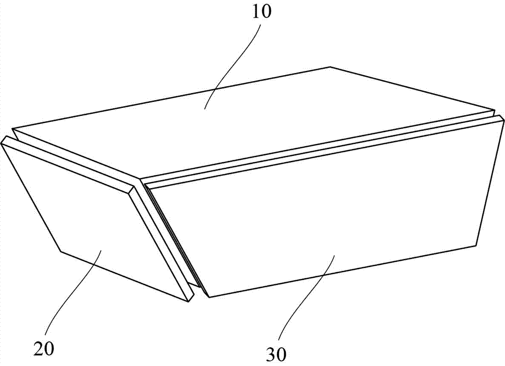
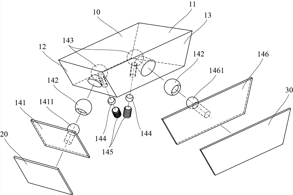
[0045] The angle adjustment device of the base in this embodiment is a ball joint type I, figure 2 is the outline drawing of this embodiment, showing the appearance shape of this embodiment, image 3 It is an exploded view of this embodiment, showing the internal structure and assembly relationship of this embodiment.

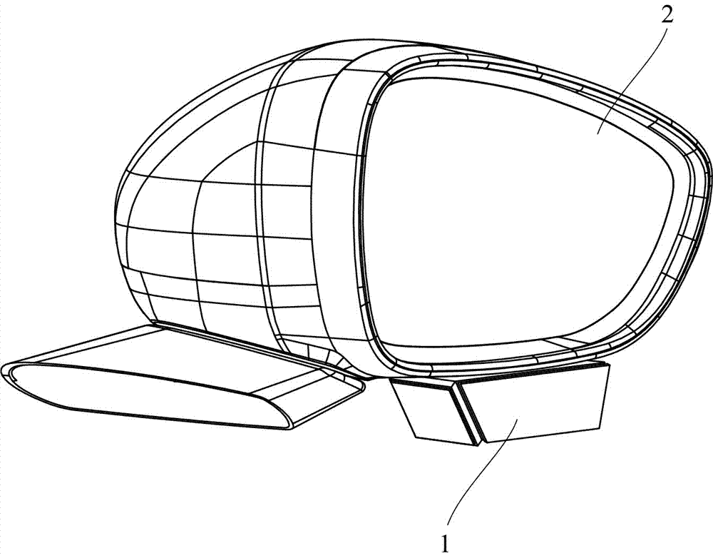
[0046] refer to image 3 , the base 10 is in the shape of a hexahedron block, and its fixed part 11 is a plane on the top, which is pasted to the lower edge of the outer frame of the rearview mirror by double-sided tape or adhesive to fix the base 10; More important, they are the front mirror mounting surface 12 and the rear mirror mounting surface 13 respectively. The front mirror mounting surface 12 makes the front mirror 20 and the front mirror mounting surface 12 parallel, and the reflection area of ​​the front mirror 20 is roughly the area near the front wheel. It is only necessary to make slight adjustments to the front mirror 20; similarly, when the r...

Embodiment 2

[0051] The angle adjustment device of the base in this embodiment is a ball joint type II, Figure 4 It is an outline drawing of this embodiment, showing the appearance shape of this embodiment.

[0052] refer to Figure 4 , the fixed part 11 connecting the base 10 and the rearview mirror is a plane at the top; the shape of the base 10 is different from that of Embodiment 1, it is no longer a block shape, but a piece with two independent adjustments hanging below The flat plate of the device; the angle adjustment device 14 is still a ball joint structure, and the adjustment of the front mirror 20 is an example. If the rear mirror 30 is not considered, the angle adjustment device 14 is made up of a curved rod bracket 147 and a ball head locking device 148, and the curved rod bracket The front end of 147 is bonded to the back of the front mirror 20, and its rear end has a ball head that is inserted into the ball socket of the ball head locking device 148. After adjusting the an...

Embodiment 3

[0056] The angle adjustment device of the base in this embodiment is a three-point adjustment structure, Figure 5 is the outline drawing of this embodiment, showing the appearance shape of this embodiment, Image 6 It is an exploded view of this embodiment, showing the internal structure and assembly relationship of this embodiment, Figure 7 Taking the adjustment of the front mirror 20 as an example to further reveal the internal structure of the three-point adjustment structure by using the sectional view.

[0057] refer to Figure 5 , the shape of the base 10 is different from that of Embodiment 1 and Embodiment 2. It is a short and thick twisted round rod, which is twisted so that the front mirror mounting surface 12 of the base 10 (refer to Image 6 ) and rear mirror mounting surface 13 (reference Image 6 ) is at an appropriate angle, where appropriate means that even if the front mirror and the rear mirror are directly attached to the two mounting surfaces, they can...


PUM


Abstract

The invention discloses a car auxiliary reflective mirror capable of seeing a front wheel and a rear wheel simultaneously. The car auxiliary reflective mirror is used for providing assistance when side parking is conducted on a car so that the car can be avoided to run into a kerb. The car auxiliary reflective mirror comprises a base, a front mirror body and a rear mirror body. The top of the baseis provided with a fixing part which is connected with the lower edge of an outer frame of a rearview mirror of the car, and the fixing part comprises a plane or a camber surface at the top of the base, a screw matching part, a thread matching part, a plug pin matching part and a buckle matching part. The front mirror body and the rear mirror body are mounted on the base, and located at the samehorizontal plane, the front mirror body is located on one side close to a driving cab, and the rear mirror body is located on one side away from the driving cab. The base is provided with an adjustingdevice for finely adjusting the angles of the front mirror body and the rear mirror body, wherein the adjusting device can serve as the basis for researching and developing an electric controlled adjusting device. The car auxiliary reflective mirror has the advantages that the reflective mirror is mounted at the lower edge of the outer frame of the rearview mirror, so that the valuable reflectionarea of the rearview mirror is not occupied. The ground partial areas near the front wheel and the rear wheel can be observed through the front mirror body and the rear mirror body simultaneously, and observing of the rearview mirror by a driver cannot be influenced.

Description

technical field [0001] The invention belongs to the field of auto parts, and relates to an auxiliary reflector for an automobile. Through the auxiliary reflector, the driver can see the ground area near the front and rear wheels of the automobile at the same time, so as to avoid bumping into curbs when parking sideways. Background technique [0002] Car side parking is a demanding driving technique. If you don’t pay attention to it, the wheels will be pressed against the curb. It is easy to squeeze the meridians on the side of the tires, increase the chance of blown tires when driving at high speed, and make it easier to damage the wheels. Bumps damage the appearance of the vehicle, and even old drivers are prone to make mistakes, so people are always careful when parking, because they really don't know the distance between the right tire and the curb, bumps are inevitable. The number of vehicles in modern cities is increasing rapidly, and a large number of cars are parked o...

Claims


Application Information

Patent Timeline
Patent Type & Authority Applications(China)
IPC IPC(8): B60R1/08
Inventor 向英特
Owner 向英特
Why Eureka
Try Eureka