
Control method and system for dual transformers

A control method and dual-transformer technology, which are applied in electrical components, emergency power supply arrangements, circuit devices, etc., can solve the problem of inability to achieve rapid fault isolation and user power supply recovery, and achieve the effect of economical operation.

Inactive Publication Date: 2017-12-19
STATE GRID SHANDONG ELECTRIC POWER COMPANY RIZHAOPOWER SUPPLY +1
View PDF8 Cites 0 Cited by
  • Summary
  • Abstract
  • Description
  • Claims
  • Application Information

AI Technical Summary

Problems solved by technology

Due to the lack of intelligent control measures, once a fault occurs inside the transformer or its high-voltage side, it cannot achieve fast fault isolation and user power supply restoration

Method used


Image

  • Control method and system for dual transformers
  • Control method and system for dual transformers

Examples


Embodiment Construction

[0019] The following description of the embodiments refers to the accompanying drawings to illustrate specific embodiments in which the invention may be practiced. The directional terms mentioned in the present invention, such as "up", "down", "front", "back", "left", "right", "top", "bottom", etc., are only for reference to the attached drawings. direction. Therefore, the directional terms used are used to illustrate and understand the present invention, but not to limit the present invention.

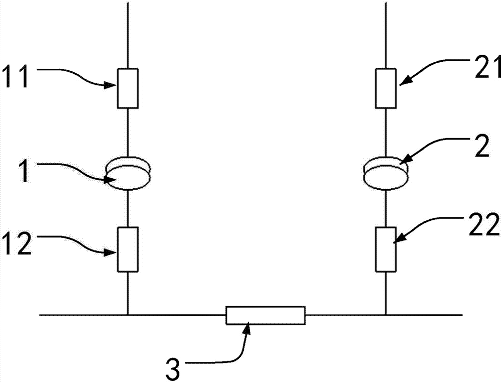
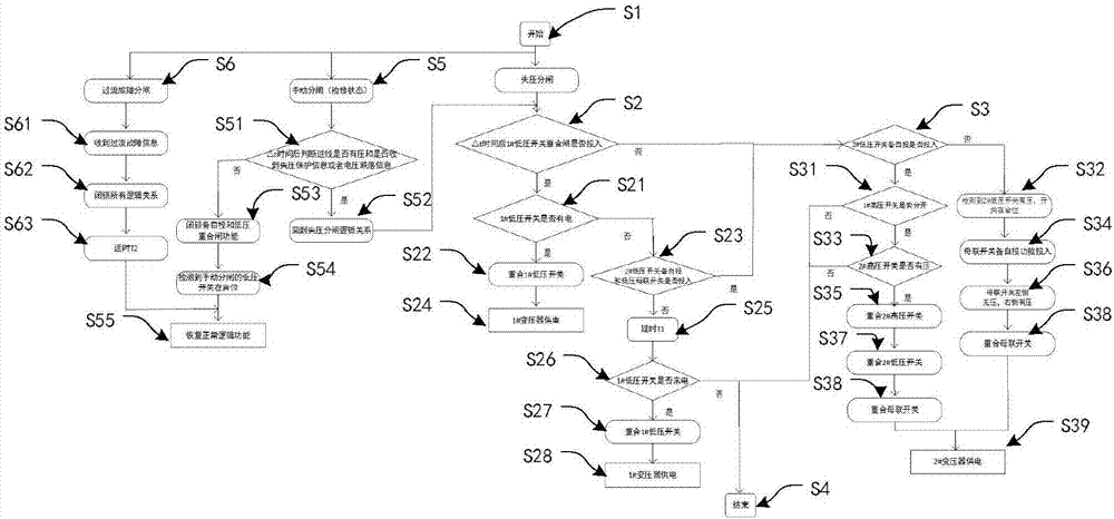
[0020] Examples such as figure 1 and figure 2 As shown, a dual-transformer control system includes a first transformer 1 including a first high-voltage switch 11 and a first low-voltage switch 12; a second transformer 2 including a second high-voltage switch 21 and a second low-voltage switch 22; a low-voltage bus tie The switch 3 is connected between the low-voltage terminal of the first transformer 1 and the low-voltage terminal of the second transformer 2; the voltage transform...


PUM


Abstract

The invention discloses a control method and system for dual transformers, which is used for detecting a running state of the system and selecting a corresponding scheme according to the running state. When a low-voltage side of each transformer losses voltages and trips, power supply can be automatically restored within relatively short time, a power supply worker does not need to run to a site for manual operation, and reliable, safe and economic running is truly achieved.

Description

technical field [0001] The invention relates to the field of automatic control of power systems, in particular to a double transformer control method and system. Background technique [0002] With the development of the economy, the user's demand for electricity has increased, and higher requirements have been put forward for the reliability of power supply. In many places in China, dual transformers serve as backup for each other to supply power to users, and the switching of these transformers is done manually. Since no intelligent control measures are taken, once a fault occurs inside the transformer or its high-voltage side, fast fault isolation and user power supply restoration cannot be achieved. Contents of the invention [0003] The purpose of the present invention is to provide a double transformer control method, overcome the existing problems in the prior art, and provide a method capable of intelligently monitoring and controlling the operation status of the d...

Claims


Application Information

Patent Timeline
IPC IPC(8): H02J9/06
CPCH02J9/061
Inventor 任力程云祥王晓梅郁章伟潘曰涛贾廷波李志军李鹏
Owner STATE GRID SHANDONG ELECTRIC POWER COMPANY RIZHAOPOWER SUPPLY
Learn More