
Double-body torsional spring forming device

A forming device and torsion spring technology, applied in the field of double-body torsion spring forming devices, can solve the problems of reducing the service life of double-body torsion springs 6, easily scratching spring wires, and greatly changing the distance between spring wires and deformation, so as to save production Process and production equipment, improve production efficiency and pass rate, and improve the effect of overall service life

Pending Publication Date: 2017-12-19
CHONGQING WANGJIANG IND
View PDF18 Cites 2 Cited by
  • Summary
  • Abstract
  • Description
  • Claims
  • Application Information

AI Technical Summary

Problems solved by technology

[0005] The existing technical problem of making like this is: on the cutting machine, the operator steps on the pedal to drive the cutting knife to insert the left spring body 6-2 and the initial shape of the right spring body 6-3 of the double-body torsion spring 6, so that It produces plastic deformation to form a pitch T, etc. Due to the different strengths, the formed pitch T is also uneven. If the pitch T is too large, it cannot be made smaller, which will cause the double-body torsion spring 6 to be scrapped, and the pass rate is relatively low. Low
Simultaneously, when the operator picks the pitch T, due to the force value applied between the initial shape of the left spring body 6-2 and the right spring body 6-3 of the double-body torsion spring 6 Not the same, if the applied force value is small, the distance between adjacent spring wires will not change, and cannot be deformed to form the required pitch T. If the applied force value is large, the distance between adjacent spring wires will not change. If the change is large and the deformation is too large, the formed pitch T will be too large, exceeding the specified range, failing to meet the quality requirements, and the quality is low
Then, the force value applied to the adjacent spring wires of the left spring body 6-2 and the right spring body 6-3 of the double-body torsion spring 6 must gradually increase from small to large, and the system can be picked repeatedly for many times. To form a specified range of pitch T, the labor intensity is high and the production efficiency is low
In addition, the operator's skill requirements are relatively high, and the operator must be very careful. A little carelessness will cause the double-body torsion spring 6 to fail due to the unqualified pitch T of the left spring body 6-2 and the right spring body 6-3. scrapped
In addition, when the cutting knife is inserted into the initial shape of the left spring body 6-2 and the right spring body 6-3 of the double-body torsion spring 6 to produce plastic deformation and form the pitch T, the cutting knife is easy to scratch the spring The surface of the wire, leaving scars, reducing the service life of the entire double-body torsion spring 6 and resulting in poor appearance quality

Method used


Image

  • Double-body torsional spring forming device
  • Double-body torsional spring forming device
  • Double-body torsional spring forming device

Examples


Embodiment Construction

[0024] Preferred embodiments of the present invention will be described in detail below in conjunction with the accompanying drawings.

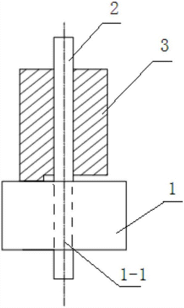
[0025] see Figure 4 to Figure 7 , the dual-body torsion spring forming device of the present invention includes a base 1 , a forming shaft 2 and a forming sleeve 3 . Depend on Figure 4 to Figure 7 It can be seen that the present invention also includes a handle 4, the longitudinal thickness of the base 1 is adapted to the length L1 of the middle torsion arm 6-4 of the double-body torsion spring 6, and a longitudinal connection through hole 1-1 is provided on it, and one side thereof There is a through groove 1-3 that runs through the top and bottom and matches the shape and diameter of the spring wire of the double-body torsion spring 6. The forming shaft 2 includes the forming shaft body 2-1 on the upper part and the smooth shaft body 2 on the lower part. -2, the length of the forming shaft body 2-1 is adapted to the length of the left s...


PUM


Abstract

The invention provides a double-body torsional spring forming device. The longitudinal thickness of a base adapts to the length of a middle torsional arm of a double-body torsional spring; one side of the base is provided with a through groove which is through up and down and is matched with a spring wire of the double-body torsional spring in shape and diameter; the length of a forming shaft body of a forming shaft adapts to the length of a left spring body and a right spring body of the double-body torsional spring; the diameter of a smooth shaft body of the forming shaft adapts to the inner diameter of the left spring body and the right spring body of the double-body torsional spring; the bottom of a forming sleeve is provided with a longitudinal through hole with the hole diameter corresponding to the inner diameter of the left spring body and the right spring body of the double-body torsional spring and slightly greater than the diameter of the smooth shaft body of the forming shaft; a connection portion is arranged outside the bottom of the forming sleeve; the forming shaft body of the forming shaft is sleeved with the forming sleeve; a thread on a threaded hole of the forming sleeve is engaged with a matched thread on the periphery of the forming shaft body; the lower end of the smooth shaft body of the forming shaft downwards penetrates through the longitudinal through hole in the bottom of the forming sleeve and a longitudinal connection through hole of the base; the lower portion of the smooth shaft body is fixedly assembled in the longitudinal connection through hole; and a handle is connected to the outer portion of the forming sleeve.

Description

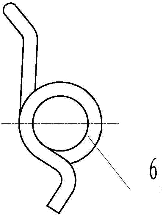
technical field [0001] The invention relates to a spring forming device, in particular to a double-body torsion spring forming device. Background technique [0002] Among the many torsion springs, there is a double-body torsion spring, see figure 1 with figure 2 As shown, the double body torsion spring 6, which includes a door-shaped middle torsion arm 6-4 with a length of L1, is symmetrically connected to the left and right lower ends of the middle torsion arm 6-4, extends horizontally outwards and has a length, section The left torsion spring body 6-2 and the right torsion spring body 6-3 that are all equal in diameter apart from T, inside and outside diameter and spring wire. The overall length L2 of the double body torsion spring 6 is equal to the sum of the length L1 of the middle torsion arm 6-4, the length of the left torsion spring body 6-2 and the length of the right torsion spring body 6-3. Usually, this two-body torsion spring 6 adopts such as image 3 The do...

Claims


Application Information

Patent Timeline
IPC IPC(8): B21F3/04
CPCB21F3/04Y02E10/72
Inventor 韦延青雷丽芳
Owner CHONGQING WANGJIANG IND
Learn More