Anti-inverted base of fire extinguisher

A fire extinguisher and fall prevention technology, which is applied in fire rescue and other directions, can solve the problems of fire extinguishers easily falling to the ground, etc., and achieves the effect of being difficult to fall and easy to use.

Inactive Publication Date: 2017-12-08
滁州恒通磁电科技有限公司
View PDF10 Cites 1 Cited by
  • Summary
  • Abstract
  • Description
  • Claims
  • Application Information

AI Technical Summary

Problems solved by technology

[0003] In view of the above-mentioned shortcomings of the prior art, the object of the present invention is to provide an anti-falling base of a fire extinguisher, which is used to solve the problem that the fire extinguisher is easy to fall to the ground in the prior art

Method used


Image

  • Anti-inverted base of fire extinguisher
  • Anti-inverted base of fire extinguisher

Examples


specific Embodiment approach

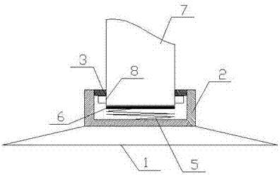
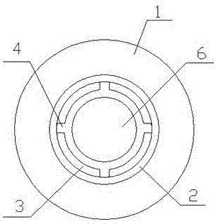
[0019] Specific implementation method: During use, put the fire extinguisher on the top plate 6, align the four stoppers 8 with the four bayonets 4 respectively, press down on the fire extinguisher, when the stoppers 8 pass through the bayonets 4 and enter the slot 2 When inside, rotate the fire extinguisher so that the stop block 8 and the bayonet socket 4 are misplaced, so that the fire extinguisher will not fall to the ground from the draw-in slot 2 under a small external force.


PUM


Abstract

The invention discloses an anti-inverted base of a fire extinguisher. The anti-inverted base of the fire extinguisher comprises a chassis, a slot, a retainer ring, bayonets, a spring, a top plate, the fire extinguisher and limiting blocks. The chassis is fixed to the ground. The slot is fixed into the upper plane of the chassis through bolts; the retainer ring is welded to the upper end of the inner side wall of the slot; four bayonets are formed in the retainer ring; the four bayonets form a square; a gap exists between the retainer ring and the inner wall of the slot; the spring is fixed to the bottom of the inner wall of the slot through bolts; the top plate is fixed to the upper end of the spring through bolts; and four limiting blocks are fixed to the lower end of the outer side wall of the fire extinguisher. The anti-inverted base of the fire extinguisher disclosed by the invention has the advantages of being convenient to take and unlikely to invert and the like.

Description

technical field [0001] The invention relates to a fire extinguisher base, in particular to an anti-falling base of a fire extinguisher. Background technique [0002] Fire extinguishers are fire-fighting equipment specially used to extinguish fires. Fire extinguishers can be seen in various places in life, but many fire extinguishers are placed directly on the ground without fixed devices, and they are easy to be knocked over. The pressure inside the fire extinguisher is different from the outside atmospheric pressure. , The violent collision when falling to the ground may cause the danger of fire extinguisher leakage. Contents of the invention [0003] In view of the above-mentioned shortcomings of the prior art, the object of the present invention is to provide an anti-falling base of a fire extinguisher, which is used to solve the problem that the fire extinguisher is easy to fall to the ground in the prior art. [0004] In order to achieve the above purpose and other r...

Claims


Application Information

Patent Timeline
Patent Type & Authority Applications(China)
IPC IPC(8): A62C13/78
CPCA62C13/78
Inventor 丛建华胡文杰
Owner 滁州恒通磁电科技有限公司
Why Eureka
Try Eureka