One-way clutch

A technology of one-way clutches and clutches, which is applied to one-way clutches, clutches, mechanical equipment, etc., and can solve problems such as the inability to control the reverse rotation of the output part

Inactive Publication Date: 2017-11-28
池尚勋
View PDF9 Cites 2 Cited by
  • Summary
  • Abstract
  • Description
  • Claims
  • Application Information

AI Technical Summary

Problems solved by technology

[0013] For this reason, the problem to be solved by the present invention is that the existing one-way clutch can not control the reverse rotation of the output part using the input part due to the intelligent one-way rotation of the output part utilizing the input part.

Method used


Image

  • One-way clutch
  • One-way clutch
  • One-way clutch

Examples


Embodiment Construction

[0034] The terms or words used in this specification and the scope of the claims should not be limited to the usual or dictionary meanings to be interpreted, but the inventor should consider the best way to explain his own invention and properly define the terms and concepts, and interpret them as meanings and concepts consistent with the technical ideas of the present invention. concept.

[0035] Therefore, the embodiment shown in this description and the structure in the accompanying drawings are only one of the preferred embodiments of the present invention, and cannot represent the technical idea of ​​the present invention. equivalents or modifications.

[0036] Describe in detail below in conjunction with accompanying drawing:

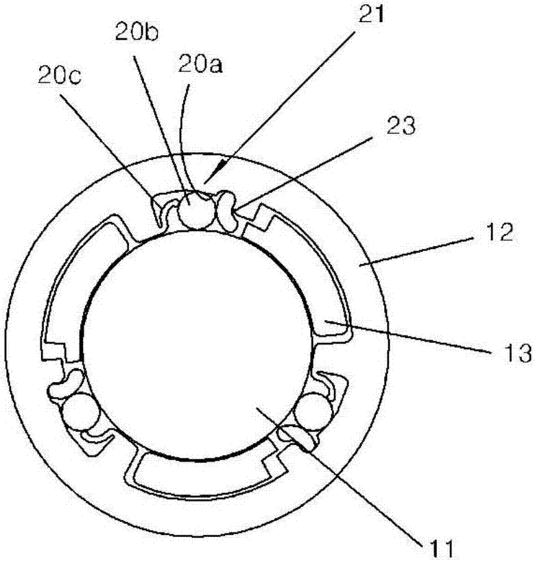
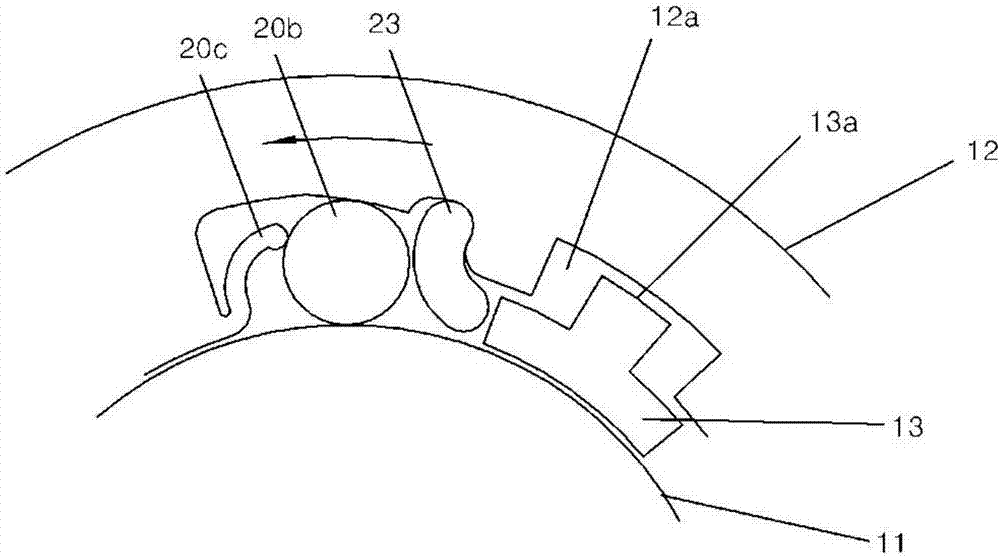
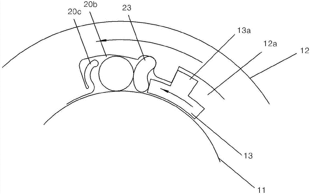
[0037] The one-way clutch of the present invention transmits both the reverse and forward rotational forces of the input part to the output part.

[0038] That is, the one-way clutch of the present invention includes a fixed part 11 located on e...


PUM


Abstract

The present invention relates to a one-way clutch in which a forward key (20b) of an output part (12) is locked and a bi-directional rotation of the output part (12) can be controlled by means of an input part (13). That is, the present invention relates to a one-way clutch comprising: a fixation part (11) provided at either an inner side or an outer side of a clutch part; an output part (12) provided at a position corresponding to the fixation part (11); an input part (13) provided between the fixation part (11) and the output part (12); and a forward key means (21) provided on the output part (12) for locking a forward key of the output part (12). Accordingly, the present invention comprises an input part (13) provided between the fixation part (11) and the output part (12); and a forward key means (21) for key-locking the output part (12) in the forward direction, such that the forward rotation of the output part (12) is key-locked by means of the forward key means (21) and the key locking of the forward key means (21) is released by means of the input part (13), so that the output part (12) is rotated in the forward direction by means of the input part (13) and the output part (12) is rotated in the reverse direction by means of the input part (13). As such, the present invention has an effect wherein the output part (12) is rotated in the forward and reverse directions by means of the input part (13).

Description

technical field [0001] The present invention relates to a one-way clutch. Specifically, the one-way clutch involved in the present invention includes a fixed part located on either side of the inner edge and outer edge of the clutch part, and an output terminal located at the corresponding position of the fixed part. part, the input part arranged between the fixed part and the output part, and the positive block device arranged on the output part and making the output part positively lock. Its purpose is to complete the positive block locking of the output part, and use the input part to control the bidirectional rotation of the output part. [0002] Another object of the present invention is to complete the forward and reverse block locking of the output part by having a reverse block device located in the reverse direction of the forward block device, which can reversely lock the output part, and use the input part to control Bi-directional rotation of the output part. [...

Claims


Application Information

Patent Timeline
Patent Type & Authority Applications(China)
IPC IPC(8): F16D41/064F16D41/06
CPCF16D41/06F16D41/064F16D41/088F16D41/066F16D41/07
Inventor 池尚勋
Owner 池尚勋
Why Eureka
Try Eureka