Method for implementing self-stabilizing control module

A technology of a control module and an implementation method, which is applied in the directions of reactive power compensation, AC network voltage adjustment, etc., can solve the problems of lack of versatility and universal applicability, and the inability to achieve precise control of feeder voltage.

Inactive Publication Date: 2017-11-24
周万坤 +2
View PDF3 Cites 0 Cited by
  • Summary
  • Abstract
  • Description
  • Claims
  • Application Information

AI Technical Summary

Problems solved by technology

However, this device is a passive solution, and the autotransformer used cannot achieve precise control of the feeder voltage, and is suitable for rough adjustment in remote areas, and has no versatility and universal applicability.

Method used


Image

  • Method for implementing self-stabilizing control module
  • Method for implementing self-stabilizing control module
  • Method for implementing self-stabilizing control module

Examples


Embodiment Construction

[0025] The preferred embodiments of the present invention are given below in conjunction with the accompanying drawings to describe the technical solution of the present invention in detail.

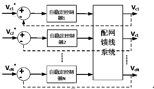
[0026] like Figure 1 to Figure 2 As shown, the implementation method of the self-stabilizing control module of the present invention comprises the following steps:

[0027] Step 1. First, control the integral link according to the following equations (1) and (2):

[0028] ……(1)

[0029] ……(2)

[0030] Among them, Kp and Ki are PID adjustment parameters, is the measured voltage, is the set voltage; is the error value between the two, is the control voltage, e represents a mathematical constant, which is the base of natural logarithm, approximately equal to 2.718281828, t represents the current time, t 0 Represents the last sampling time.

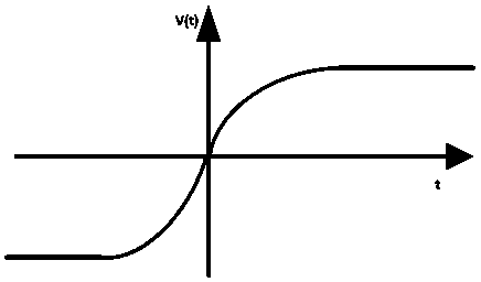
[0031] Step 2, calculating according to the self-stabilizing nonlinear curve;

[0032] Step 3, design the self-stabilizing control al...


PUM


Abstract

The invention discloses a method for implementing a self-stabilizing control module. The method comprises the following steps that an integral step is controlled, calculation is conducted according to a self-stabilizing non-linear curve diagram, and a self-stabilizing control algorithm is designed; when a voltage preset value is much larger than a measured voltage value, quick integral control is conducted, multiple sub-modules cut in preferentially, and the voltage preset value and the actually measured voltage value are within a certain range; then a sub-module system can be made to smoothly cut in or cut out by a self-stabilizing control module according to the designed control algorithm. According to the method for implementing the self-stabilizing control module, the problem of voltage dips caused by a dynamic load and gradual lowering of the feeder voltage along a feeder line can be solved, needs of a user can be met, and the control on any nodes can be turned on or off flexibly and autonomously when / where it is needed most, so that reactive power optimization and peak control of the voltage can be achieved.

Description

technical field [0001] The invention relates to a method, in particular to a method for realizing a self-stabilizing control module. Background technique [0002] The reactive power compensation equipment of the high-voltage 10 kV system is generally installed in the substation and adopts the centralized compensation and adjustment method, but the branches of the high-voltage 10 kV feeder are scattered and long, resulting in poor control effect at the end of the line. With the widespread application of nonlinear loads, the access of distributed energy sources, and the imbalance of user loads and other factors, the actual instantaneous reactive power of the grid system is always in high-frequency changes, and global optimization cannot be achieved, resulting in overall power decline in quality. [0003] In order to solve the problem of power quality control in the smart distribution network, many equipments to improve the quality of the power grid have been developed at home...

Claims


Application Information

Patent Timeline
IPC IPC(8): H02J3/16
CPCH02J3/16Y02E40/30
Inventor 周万坤高洪兴高远刘金松
Owner 周万坤
Why Eureka
Try Eureka