
Duct pollination device of multi-rotor type aircraft and pollination method thereof

A technology of multi-rotor aircraft and pollination device, which is applied in the direction of aircraft, rotorcraft, botanical equipment and methods, etc., can solve the problems of complex mechanism of airborne devices, reduced efficiency of pollination operation of drones, poor pollination effect, etc., to achieve Improve pollination efficiency, improve efficiency, and facilitate the effect of dispersal

Active Publication Date: 2017-11-17
SOUTH CHINA AGRI UNIV
View PDF7 Cites 6 Cited by
  • Summary
  • Abstract
  • Description
  • Claims
  • Application Information

AI Technical Summary

Problems solved by technology

However, the direction of pollen diffusion from the male plant to the female plant during pollination is mainly along the horizontal direction of the plant canopy plane, so the vertical wind field generated by the rotor of the aircraft itself will directly affect the effective horizontal wind required for pollination. The problems in the field make the operation efficiency of UAV pollination lower, and the pollination effect is not good
In addition, the mechanism of the existing airborne device for UAV pollination operations is complicated, and it is necessary to install air ducts and fixing frames

Method used


Image

  • Duct pollination device of multi-rotor type aircraft and pollination method thereof
  • Duct pollination device of multi-rotor type aircraft and pollination method thereof
  • Duct pollination device of multi-rotor type aircraft and pollination method thereof

Examples


Embodiment Construction

[0038] The present invention will be further described in detail in conjunction with the accompanying drawings and specific embodiments.

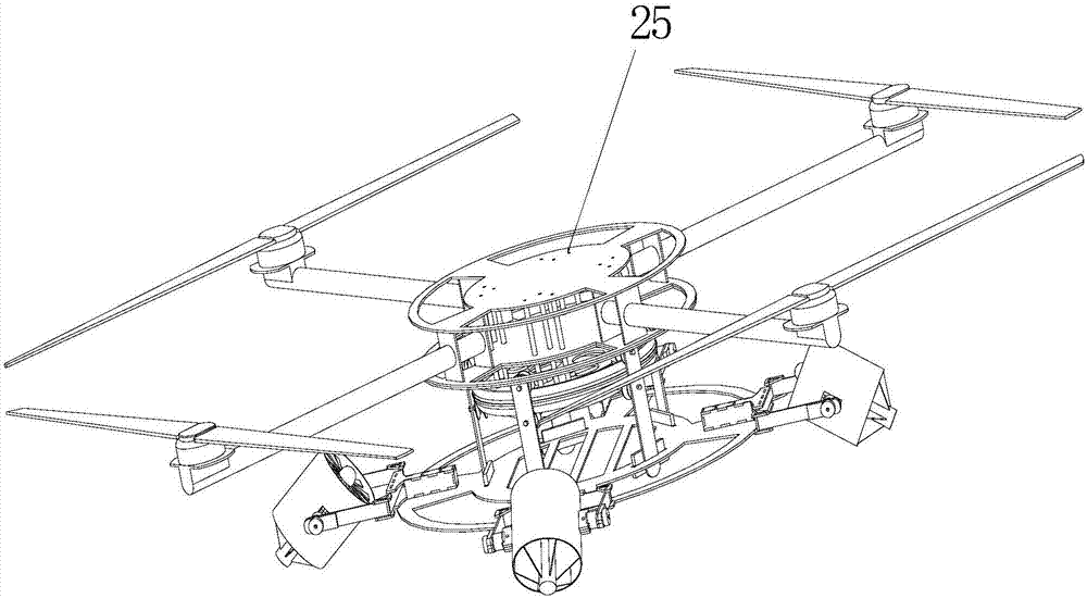
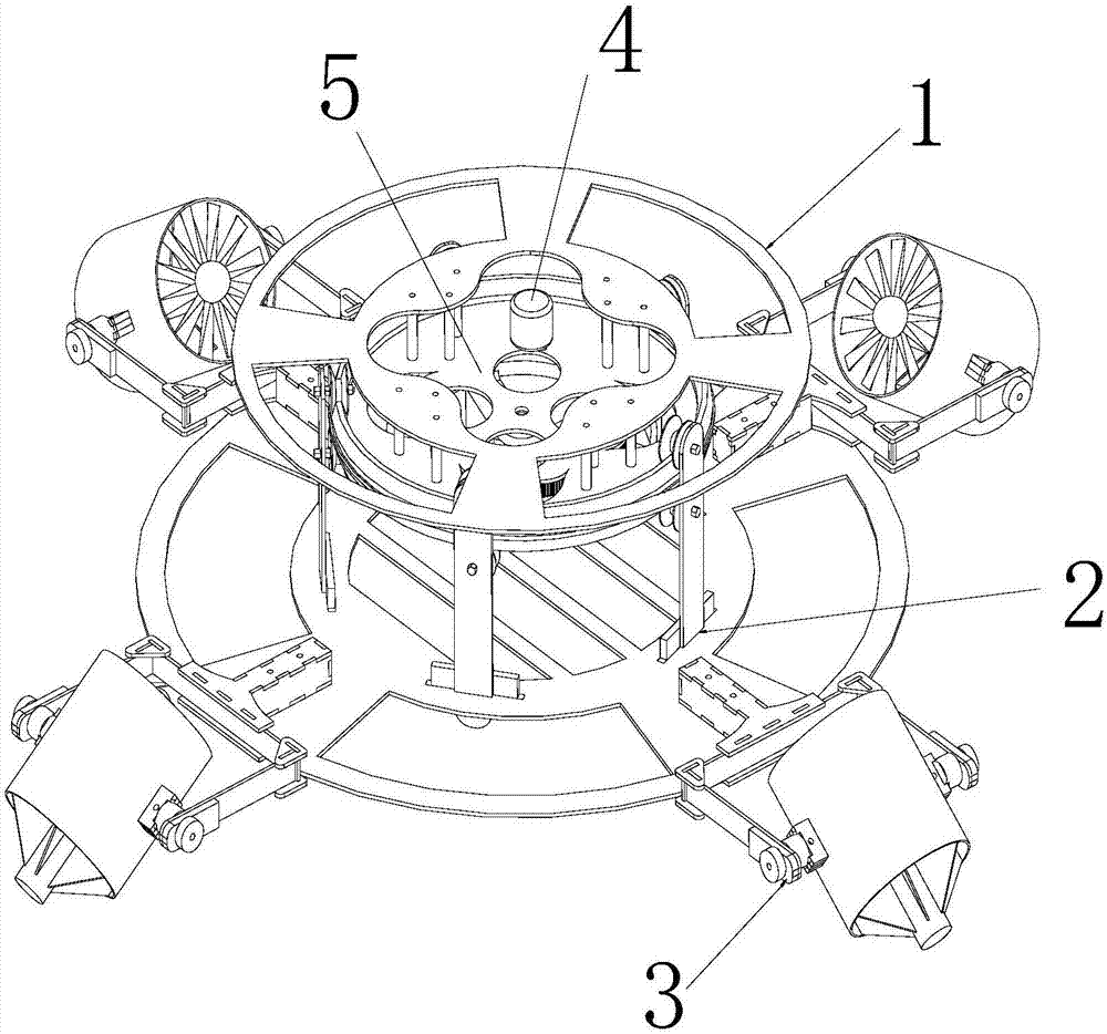
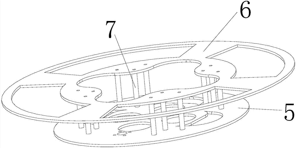
[0039] combine Figure 1 to Figure 12 As shown, a ducted pollination device for a multi-rotor aircraft includes a connecting frame with a circular plate, a circular guide rail, a rotating frame, a motor, a driving gear, a driven gear, a circular wheel, and a plurality of ducted fans mechanism. The aircraft is installed on the upper end of the connecting frame, the circular plate is located at the lower end of the connecting frame, the circular plate is embedded in the inner wall of the circular guide rail, the driven gear is fixed on the upper end surface of the circular wheel, the output end of the motor is connected with the driving gear, and the driving gear Mesh with the driven gear, the driven gear is located under the circular plate, the rotating frame is equipped with a plurality of vertical plates distributed along the circumferent...


PUM


Abstract

The invention relates to a duct pollination device of a multi-rotor type aircraft. The aircraft is installed at the upper end of a connecting frame, a circular plate is located at the lower end of the connecting frame and is embedded into the peripheral inner wall of a circular guide rail, a driven gear is fixed at the upper end face of a circular wheel disc, the output end of a motor is connected to a driving gear, the driving gear is meshed with the driven gear, a rotary frame is provided with multiple stand plates distributed in the peripheral direction, each stand plate is provided with an upper idler wheel mechanism and a lower idler wheel mechanism which are arranged up and down, an idler wheel of the upper idler wheel mechanism is in coordination with an upper guide rail of the circular guide rail, an idler wheel of the lower idler wheel mechanism is in coordination with a lower guide rail of the circular guide rail, one end of the lower idler wheel mechanism is fixed on the peripheral side face of the circular wheel disc, the other end of the lower idler wheel mechanism is fixed on the stand plates, multiple duct fan mechanisms are arranged at the lower portion of the rotary frame in the peripheral direction. The invention further relates to a pollination method. The duct pollination device of the multi-rotor type aircraft has the good pollination effect, and belongs to the technical field of field pollination operation.

Description

technical field [0001] The invention relates to the technical field of farmland pollination operations, in particular to a ducted pollination device for multi-rotor aircraft and a pollination method thereof. Background technique [0002] Assisted pollination is an operation with strong technical requirements, high precision requirements and tight time requirements. The pollination effect is obviously affected by various factors, and high requirements are put forward for the pollination method. At present, artificial assisted pollination includes human and mechanical methods. Human assisted pollination is not only labor-intensive and inefficient, but also has obvious uneven pollination, which reduces the yield of seed production and takes a lot of time; mechanical pollination replaces human pollination. Can effectively improve work efficiency. But the existing mechanical pollination is mainly limited to two forms of hand-held mechanical pollination and walking mechanical po...

Claims


Application Information

Patent Timeline
Patent Type & Authority Applications(China)
IPC IPC(8): A01H1/02B64C27/08
CPCA01H1/02A01H1/027B64C27/08
Inventor 李继宇周志威于晴晴陈铭楠肖基创
Owner SOUTH CHINA AGRI UNIV
Learn More