Pin base, pin damage testing device in chamber and method thereof

A technology of damage detection and pin seat, applied in the direction of error detection/correction, generation of response errors, instruments, etc., can solve problems such as poor glass engineering, glass cannot be laid flat, pin head damage, etc., and achieve the effect of reducing glass engineering defects

Inactive Publication Date: 2017-09-29
SEMISYSCO CO LTD
View PDF9 Cites 1 Cited by
  • Summary
  • Abstract
  • Description
  • Claims
  • Application Information

AI Technical Summary

Problems solved by technology

[0003] The pin head of this kind of pin is frequently damaged due to the structural characteristics of the pin. The damaged pin head is arranged on the upper part of the workbench, so the glass delivered to the workbench due to engineering needs cannot be laid flat.
As a result, poor glass engineering

Method used


Image

  • Pin base, pin damage testing device in chamber and method thereof
  • Pin base, pin damage testing device in chamber and method thereof
  • Pin base, pin damage testing device in chamber and method thereof

Examples


Embodiment Construction

[0035] The singular expressions used in this specification also include the plural expressions unless otherwise specified in the specification. In this specification, terms such as "consisting" or "comprising" should not be understood as necessarily including all the components or steps described in the specification, but should be understood as not including some of the components or steps, or understanding It may also include other constituent elements or steps. In addition, terms such as "...part" and "module" described in the specification indicate a unit that processes at least one function or action, which can be realized by hardware or software, or by combining hardware and software.

[0036] Embodiments of the present invention will be specifically described below with reference to the drawings.

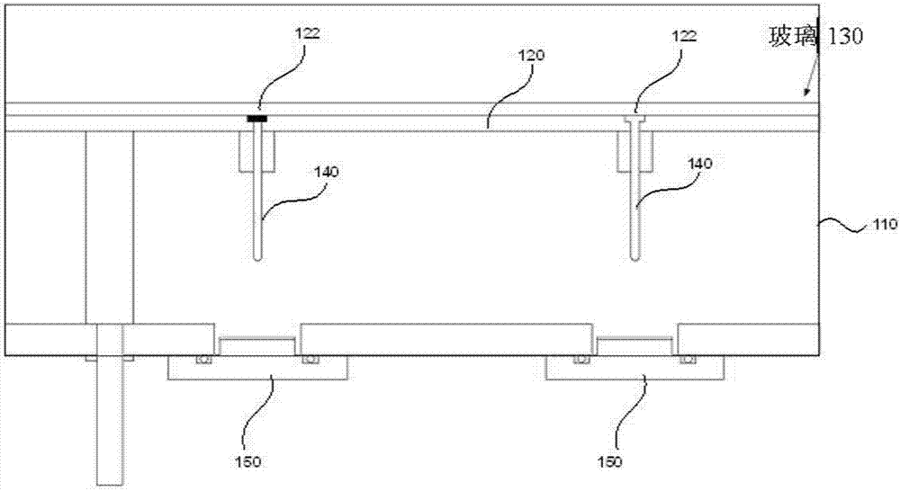
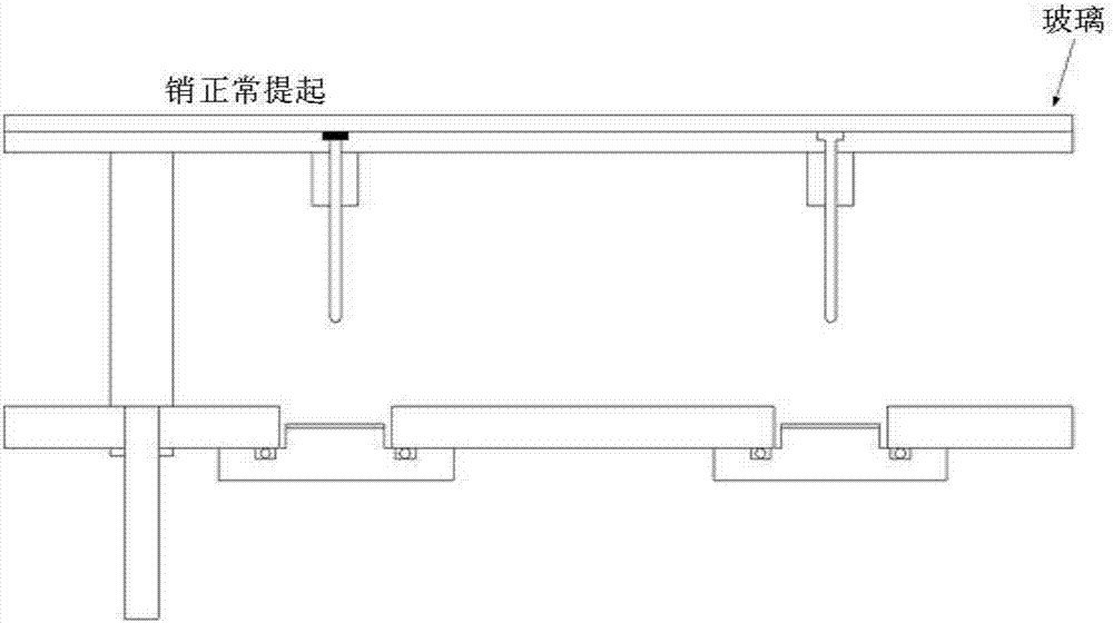
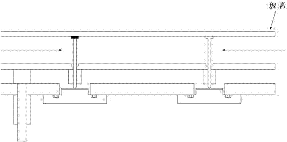
[0037] In order to illustrate the pin damage detection device inside the cavity according to an embodiment of the present invention, the structure inside the cavity will be ...


PUM


Abstract

The invention discloses a pin damage testing device in a chamber and a method thereof. The pin damage testing device in the chamber comprises the components of a pin base which is combined with one surface of the chamber; and a light output part which irradiates an optical signal to the pin base, wherein the pin base is provided with a transparent penetrating part, and the optical signal which is output from the light output part penetrates through the transparent penetrating part of the pin base and is transmitted to a pin that is connected with a worktable, and whether the pin is damaged can be tested through analyzing the reflection pattern of the optical signal that is transmitted to the pin. The pin damage testing device in the chamber according to the invention and the method thereof can perform real-time monitoring for determining whether the pin which cannot be determined by naked eyes and is at the inner part of the chamber is damaged.

Description

technical field [0001] The invention relates to a pin damage detection device inside a cavity and a method thereof. Background technique [0002] Inside the engineering chamber is a workbench that supports the glass during engineering. This kind of workbench can be lifted and lowered inside the engineering cavity according to engineering needs, so as to move the glass to an appropriate position. The table is formed with a pin hole, and for the convenience of conveying the glass, there is a pin provided through the pin hole for lifting the glass. [0003] The pin head of this kind of pin is frequently damaged due to the structural characteristics of the pin, and the damaged pin head is arranged on the upper part of the workbench, so the glass delivered to the workbench due to engineering needs cannot be laid flat. As a result, glass engineering is defective. Contents of the invention [0004] technical problem [0005] An object of the present invention is to provide a ...

Claims


Application Information

Patent Timeline
Patent Type & Authority Applications(China)
IPC IPC(8): G06F11/07
CPCG06F11/0751
Inventor 李淳钟李东锡申河荣
Owner SEMISYSCO CO LTD
Why Eureka
Try Eureka