
Mine water damage microseismic monitoring time-space cluster analysis method

A technology for microseismic monitoring and mine water, applied in seismology, measuring devices, water resource assessment, etc., can solve the problems of lag in mine water disaster early warning methods, difficult parameters to measure, and limited application, and achieve the effect of improving intelligent early warning capabilities.

Inactive Publication Date: 2017-09-26
HEBEI COAL SCI RES INST
View PDF5 Cites 18 Cited by
  • Summary
  • Abstract
  • Description
  • Claims
  • Application Information

AI Technical Summary

Benefits of technology

In this patents describes an improved way to analyze mineral waters during drilling operations. By analyzing these waves with advanced technology such as Time Spatial Cluster Analysis or Microseismics, we can identify areas where there may be damaged zones caused by explosions or other factors affecting underground environments like tunnels. These identified sections help prevent future issues related to rock burstings and ground subsidence. Additionally, We use breakpoint detection techniques on specific locations along the seam line to determine if excavation activities have resulted in significant loss of life and economic losses due to environmental impact associated with coal mines. Overall, our approach helps improve safety measures against natural haze threatening conditions and provide valuable insights into hydraulic fracturing processes.

Problems solved by technology

This patents discusses various technical problem areas related to coal seams' impact upon safety issues during excavation operations for managing hydrasion risk (Hydrometric Hydrostatic Stress Index) caused by overfishing waters. Current solutions involve analyzing the relationship between different factors like depth and stress levels within the pit itself, including physical properties such as porous nature and permeable rocks. However, current analysis techniques have limitations when applied to deeper locations where buried layers may also contain significant quantities of water.

Method used


Image

  • Mine water damage microseismic monitoring time-space cluster analysis method
  • Mine water damage microseismic monitoring time-space cluster analysis method
  • Mine water damage microseismic monitoring time-space cluster analysis method

Examples


Embodiment

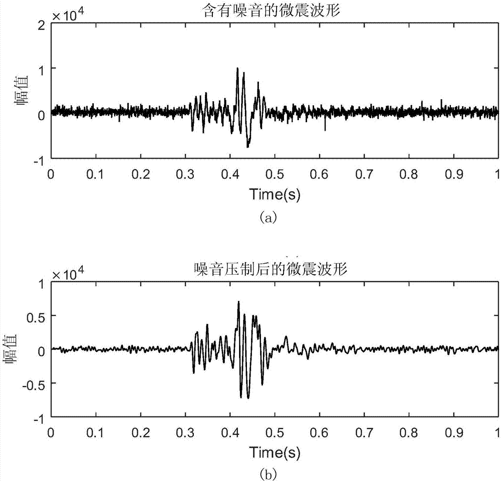
[0073] Such as figure 2 Shown is the comparison result of microseismic monitoring signal preprocessing, from figure 2 (a) It can be clearly seen that the original waveform data contains a lot of noise. After preprocessing, the figure 2 In (b), the noise interference is effectively removed, and the obtained waveform signal is mainly an effective signal generated by high-pressure water erosion and rock fracture.

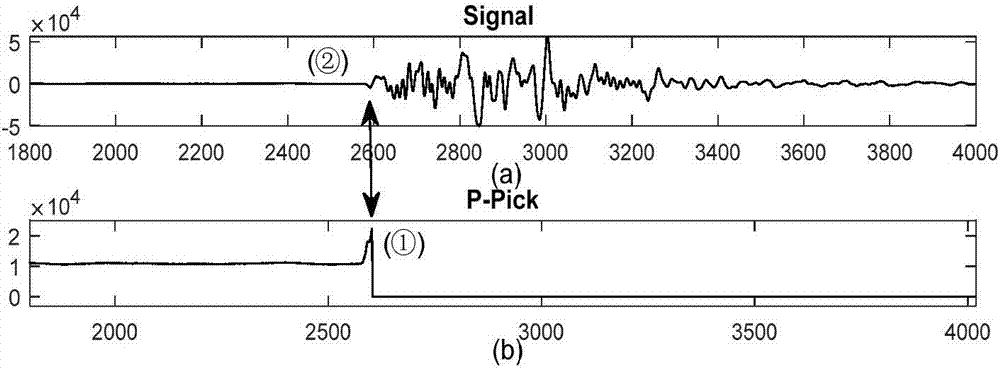
[0074] Such as image 3 Shown is the picking result of the first arrival of the microseismic signal, image 3 is the waveform data after preprocessing in step 2. Taking this data as an example to pick up the first arrival moment of the microrupture signal, at image 3 The position pointed by the double-headed arrow in the middle is the first arrival moment of the signal automatically picked up after noise removal, from image 3 The position of the local maximum point in (b) ② is the first arrival of automatic picking, which is the same as the point indicated by ...


PUM


Abstract

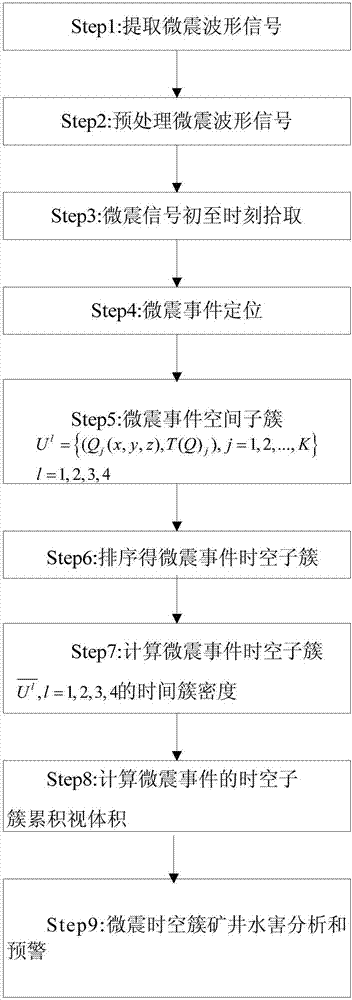
The invention relates to the field of mine water damage monitoring and water resource protection, and provides a mine water damage microseismic monitoring time-space cluster analysis method. The mine water damage microseismic monitoring time-space cluster analysis method comprises the following steps: extracting microseismic waveform signals; preprocessing the microseismic waveform signals; picking up microseismic signal beginning time; positioning microseismic events; with a floor crushed zone and a floor limestone mark layer of a stope as benchmarks, selecting a benchmark point Qi (xi, yi, zi), calculating the spatial distance between a microseismic event set and the benchmark point, and if a FORMULA is met, obtaining microseismic space cluster subsets; sorting the space cluster subsets in time sequence respectively to obtain microseismic event time-space cluster subsets. For the microseismic event groups which are randomly developed and mingled together, regularization of the microseismic events is achieved in the time domain and the space domain, that is, a microseismic time-space cluster method for describing the forming and changing processes of a water guiding passage is achieved, continuous real-time inversion of the water guiding passage, which is one of key factors causing mine water damage, in the time domain and the space domain is achieved, and thus the intelligent mine water damage prewarning capacity is greatly enhanced.

Description


Claims


Application Information

Patent Timeline
Owner HEBEI COAL SCI RES INST
Learn More