Optical module housing and optical module

A technology for optical modules and housings, applied in the field of optical module housings and optical modules, can solve the problems of environmental pollution of dust-proof devices, erosion of optoelectronic devices, loss of dust-proof devices, etc., to reduce BOM costs, avoid waste of resources, and avoid pollution Effect

Inactive Publication Date: 2017-09-15
SOURCE PHOTONICS CHENGDU
View PDF5 Cites 6 Cited by
  • Summary
  • Abstract
  • Description
  • Claims
  • Application Information

AI Technical Summary

Problems solved by technology

In the unused state, the optical interface is idle, and the dust in the air can easily enter the optical module through the optical interface, corrode the optoelectronic devices, and make it unable to work normally, so it is necessary to install a dust-proof device to seal the optical interface
At present, the dust-proof devices used for optical modules are all independent components. When sealing is required, put the dust-proof device on the optical interface, and remove it when it is not needed. This will easily cause the loss of the dust-proof device, and the dust-proof device is often difficult. Decomposed plastic structures, lost dust protection devices also cause environmental pollution

Method used


Image

  • Optical module housing and optical module
  • Optical module housing and optical module
  • Optical module housing and optical module

Examples


Embodiment Construction

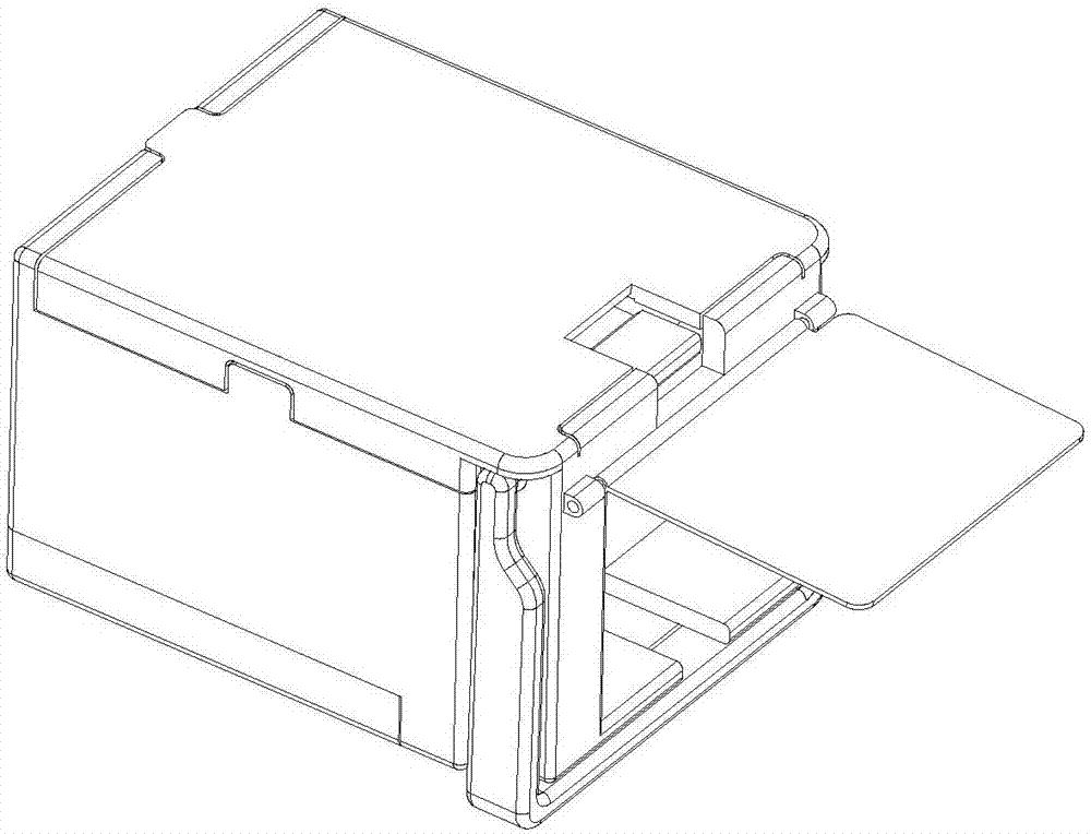
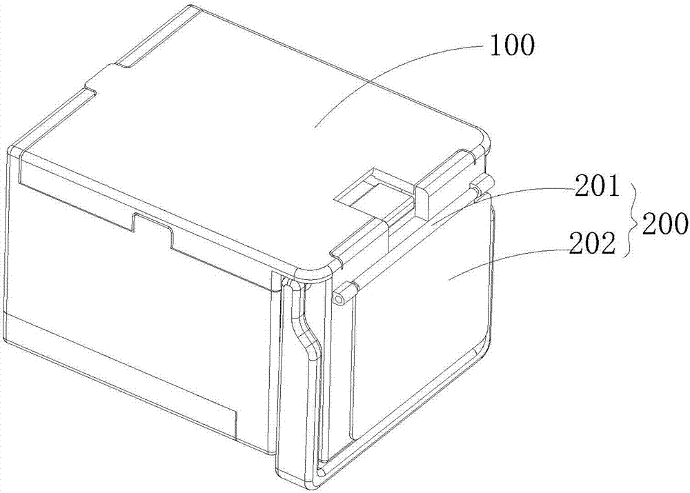
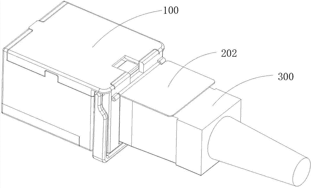
[0023] The following will clearly and completely describe the technical solutions in the embodiments of the present invention with reference to the accompanying drawings in the embodiments of the present invention. Obviously, the described embodiments are only some, not all, embodiments of the present invention. The components of the embodiments of the invention generally described and illustrated in the figures herein may be arranged and designed in a variety of different configurations. Accordingly, the following detailed description of the embodiments of the invention provided in the accompanying drawings is not intended to limit the scope of the claimed invention, but merely represents selected embodiments of the invention. Based on the embodiments of the present invention, all other embodiments obtained by those skilled in the art without making creative efforts belong to the protection scope of the present invention.

[0024] see Figure 1-3 In this embodiment, an optic...


PUM


Abstract

The present invention relates to an optical module housing and an optical module. The optical module housing comprises an optical module housing body and a dustproof part, and the dustproof part is connected with the optical module housing body to cover an optical interface formed by the optical module housing body. The optical module comprises an optical module housing and an optical transmit-receive module. According to the optical module housing and the optical module, the dustproof part is connected with the optical module housing body, the integration state is maintained to allow the dustproof part not to be easily lost so that the environment pollution and the waster of the dustproof part cannot be caused and the cost is reduced.

Description

technical field [0001] The invention relates to the technical field of communication equipment, in particular to an optical module housing and an optical module. Background technique [0002] The main function of the optical transceiver integrated module (referred to as the optical module) is to realize the photoelectric / electrical-optical conversion. It is usually composed of optoelectronic devices, functional circuits and optical interfaces. It is an important part of the optical fiber communication system. According to different packaging forms, there are mainly SFP , GBIC, XFP, etc. In the unused state, the optical interface is idle, and the dust in the air can easily enter the optical module through the optical interface, corrode the optoelectronic devices, and make it unable to work normally. Therefore, dust-proof devices need to be installed to seal the optical interface. At present, the dust-proof devices used for optical modules are all independent components. When...

Claims


Application Information

Patent Timeline
Patent Type & Authority Applications(China)
IPC IPC(8): G02B6/42
CPCG02B6/4251G02B6/4246
Inventor 曾海峰王金林侯羿
Owner SOURCE PHOTONICS CHENGDU
Why Eureka
Try Eureka