Shock absorption device of mechanical equipment

A technology of mechanical equipment and shock absorbing devices, which is applied in the direction of mechanical equipment, springs/shock absorbers, supporting machines, etc., can solve the problems of unfavorable mechanical equipment, uneven shock absorption, and insufficient shock absorption effect, so as to improve shock absorption Excellent effect, strong practicability, and easy to use

Inactive Publication Date: 2017-09-05
LIANGXI XUZHONG GENERAL MACHINERY DESIGN STUDIO
View PDF0 Cites 11 Cited by
  • Summary
  • Abstract
  • Description
  • Claims
  • Application Information

AI Technical Summary

Problems solved by technology

[0002] Mechanical equipment often vibrates during operation. This vibration will cause varying degrees of negative effects when the machine is in use, which is not conducive to the production of mechanical equipment. Therefore, many processing and manufacturing companies usually use vibration in machining The problem is studied as an important prevention problem. At present, most enterprises solve this problem by installing shock absorbers at the bottom of the mechanical equipment, but the shock absorption effect of this method is not obvious enough, and some enterprises install shock absorbers at the bottom of the machinery. device for shock absorption, but the existing shock absorption device shock absorption is not uniform enough, the shock absorption effect is not good, and the problem of mechanical vibration cannot be solved well

Method used


Image

  • Shock absorption device of mechanical equipment
  • Shock absorption device of mechanical equipment

Examples


Embodiment Construction

[0013] The following will clearly and completely describe the technical solutions in the embodiments of the present invention with reference to the accompanying drawings in the embodiments of the present invention. Obviously, the described embodiments are only some, not all, embodiments of the present invention.

[0014] Examples of the described embodiments are shown in the drawings, wherein like or similar reference numerals designate like or similar elements or elements having the same or similar functions throughout. The embodiments described below by referring to the figures are exemplary and are intended to explain the present invention and should not be construed as limiting the present invention.

[0015] In describing the present invention, it should be understood that the terms "center", "longitudinal", "transverse", "length", "width", "thickness", "upper", "lower", "front", " Back", "Left", "Right", "Vertical", "Horizontal", "Top", "Bottom", "Inner", "Outer", "Clock...


PUM


Abstract

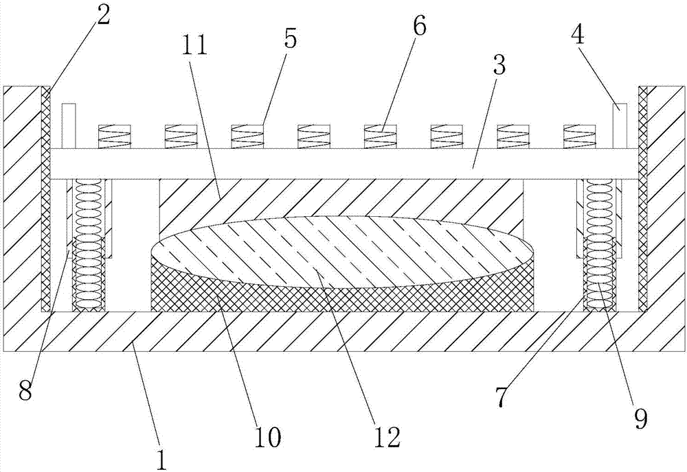
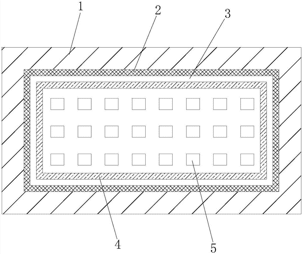
The invention discloses a shock absorbing device for mechanical equipment, comprising: a base, a mechanical equipment mounting plate, a shock absorbing rubber block, a shock absorbing strut, a support seat A, a support seat B and an ellipsoidal rubber block, the four sides of the base The inner wall is provided with an elastic rubber layer, the base is provided with a mechanical equipment installation plate, the edge of the mechanical equipment installation plate is against the elastic rubber layer, and the edge of the upper surface of the mechanical equipment installation plate is provided with a protrusion, so There are several shock-absorbing rubber blocks evenly distributed on the mechanical equipment mounting plate in the protrusion, and springs are arranged inside the shock-absorbing rubber blocks, and the four corners of the bottom of the mechanical equipment mounting plate are fixedly connected with shock-absorbing struts , the shock-absorbing strut includes a lower column, an upper column and a shock-absorbing spring, the lower column is fixedly connected to the bottom inside the base, and the upper column is fixedly connected to the bottom of the mechanical equipment mounting plate. The invention performs shock absorption from various aspects, and the shock absorption effect is outstanding.

Description

technical field [0001] The invention relates to the technical field of mechanical equipment, in particular to a shock absorbing device for mechanical equipment. Background technique [0002] Mechanical equipment often vibrates during operation. This vibration will cause varying degrees of negative effects when the machine is in use, which is not conducive to the production of mechanical equipment. Therefore, many processing and manufacturing companies usually use vibration in machining The problem is studied as an important prevention problem. At present, most enterprises solve this problem by installing shock absorbers at the bottom of the mechanical equipment, but the shock absorption effect of this method is not obvious enough, and some enterprises install shock absorbers at the bottom of the machinery. The device is used for shock absorption, but the shock absorption of the existing shock absorption device is not uniform enough, the shock absorption effect is not good, a...

Claims


Application Information

Patent Timeline
Patent Type & Authority Applications(China)
IPC IPC(8): F16M5/00F16F15/08
CPCF16M5/00F16F15/085
Inventor 倪娜
Owner LIANGXI XUZHONG GENERAL MACHINERY DESIGN STUDIO
Why Eureka
Try Eureka