
Power system stabilizer and method

A power system and stabilizer technology, applied in the direction of reducing/preventing power oscillation, reducing the asymmetry of polyphase networks, eliminating/reducing asymmetry of polyphase networks, etc. Low frequency oscillation effect, etc., to achieve the average distribution of active current, avoid weak damping, and solve the effect of low frequency oscillation

Inactive Publication Date: 2020-10-02
LIAONING UNIVERSITY OF PETROLEUM AND CHEMICAL TECHNOLOGY
View PDF1 Cites 0 Cited by
  • Summary
  • Abstract
  • Description
  • Claims
  • Application Information

AI Technical Summary

Problems solved by technology

[0003] At present, in the transmission process of the power grid, due to the long transmission distance, the damping of the power system to the oscillation will be weakened. The parameters of the power system stabilizer set for a single oscillation mode cannot compensate for the appropriate phase in other oscillation modes in which the unit participates. When the system When low-frequency oscillation occurs in medium and low-frequency oscillations, different oscillation modes have different strengths on different units, and the power system stabilizers on different units have different suppression effects on different oscillation modes. If the location of the power stabilizer is unreasonable, the installed A power system stabilizer may do little or nothing to dampen oscillations
In addition, traditional stabilizers use local information, but local information cannot reflect the oscillation mode between regions, and the effect of suppressing low-frequency oscillations between regions is low, and it is ineffective to invest in a power stabilizer for a single power plant. The generator and power generation system suppress LFO is less effective

Method used


Image

  • Power system stabilizer and method
  • Power system stabilizer and method
  • Power system stabilizer and method

Examples


Embodiment Construction

[0034] Exemplary embodiments of the present disclosure will be described in more detail below with reference to the accompanying drawings. Although exemplary embodiments of the present disclosure are shown in the drawings, it should be understood that the present disclosure may be embodied in various forms and should not be limited by the embodiments set forth herein. Rather, these embodiments are provided for more thorough understanding of the present disclosure and to fully convey the scope of the present disclosure to those skilled in the art.

[0035] In order to make the advantages of the technical solution of the present invention clearer, the present invention will be described in detail below in conjunction with the accompanying drawings and embodiments.

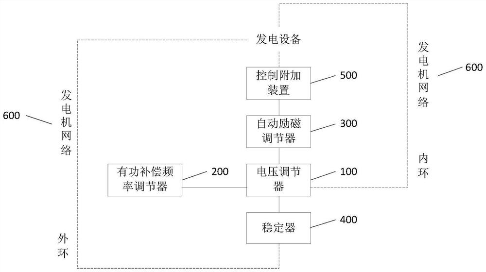
[0036] An embodiment of the present invention provides a power system stabilizer, such as figure 1 As shown, the power system stabilizer includes: a voltage regulator 100 , an active power compensation frequency reg...


PUM


Abstract

The invention discloses an electric power system stabilizer and a method, relates to the technical field of electric power, and mainly aims to overcome the shortcoming of relatively poor low-frequency oscillation suppression effect of the existing electric power system stabilizer. The electric power system stabilizer comprises a voltage regulator, an active compensation frequency regulator, an automatic exciting regulator, a stabilizer, a control additional apparatus and a generator network, wherein the stabilizer comprises a sensor, a high-frequency filter, a compensator and an amplifier; the automatic exciting regulator comprises an exciting power unit and an exciting regulator; and the voltage regulator comprises a voltage measurement comparison unit, a pulse width modulator, a low-frequency protection unit and a voltage-stabilizing circuit.

Description

technical field [0001] The invention relates to the field of electric power technology, in particular to a power system stabilizer and method. Background technique [0002] With the in-depth interconnection between power grids, the low-frequency oscillation phenomenon between regions has become a problem that cannot be ignored. In order to suppress low-frequency oscillations, power system stabilizers have emerged as the times require. It can generate a positive damping torque to overcome the negative damping torque generated in the original excitation voltage regulator, and can also extract signals related to this oscillation, such as the active power, speed or frequency of the generator, and process them to generate The additional signal is added to the excitation regulator to make the generator generate additional torque for damping low-frequency oscillation. [0003] At present, in the transmission process of the power grid, due to the long transmission distance, the dam...

Claims


Application Information

Patent Timeline
Patent Type & Authority Patents(China)
IPC IPC(8): H02J3/24H02J3/26
CPCH02J3/24H02J3/26Y02E40/50
Inventor 单海欧
Owner LIAONING UNIVERSITY OF PETROLEUM AND CHEMICAL TECHNOLOGY
Learn More