
Outdoor energy-saving controllable power supply device

A power supply device and outdoor technology, applied in the field of electric power, can solve problems such as lack of protection function, high cost of use, and potential safety hazards, and achieve the effects of convenient and quick adjustment, increased utilization rate, and increased stability

Inactive Publication Date: 2017-08-25
何胜利
View PDF9 Cites 42 Cited by
  • Summary
  • Abstract
  • Description
  • Claims
  • Application Information

AI Technical Summary

Problems solved by technology

[0002] With the development of the times, outdoor picnics and camping have become part of people's outdoor leisure sports. Outdoor picnics and camping are indispensable for electricity consumption. Because they are outdoors and limited by electricity consumption, solar power supply devices have become people's outdoor activities. Essential equipment for picnics and camping, the existing solar power supply devices do not have protection functions. There is no protective component at the power supply hole of the solar power supply device, and the battery pack in the solar power supply The hole is connected to the power supply so that the power supply hole is always energized. The power supply hole is directly exposed to facilitate the plug of the electrical equipment to be plugged in. If there is no plug inserted, if a child inserts a finger or a metal rod directly into the power supply hole , it will cause an electric shock accident, and there is a great potential safety hazard. Moreover, most of the solar panels used in the existing solar power supply devices are fixed. If it is a fixed solar panel, it will not be able to absorb sunlight better. Although there are currently some solar power generation devices that can automatically track sunlight, these devices are expensive to use and cannot meet the existing requirements. Usage requirements

Method used


Image

  • Outdoor energy-saving controllable power supply device
  • Outdoor energy-saving controllable power supply device
  • Outdoor energy-saving controllable power supply device

Examples


Embodiment Construction

[0023] The preferred embodiments of the present invention will be described in detail below in conjunction with the accompanying drawings, so that the advantages and features of the present invention can be more easily understood by those skilled in the art, so as to define the protection scope of the present invention more clearly.

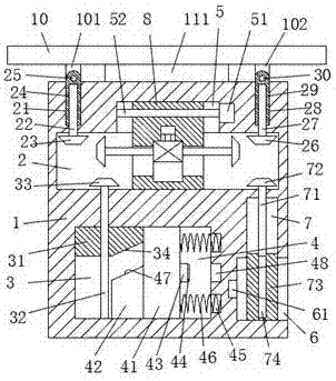
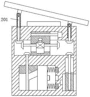
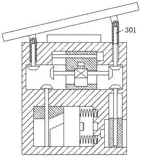
[0024] refer to Figure 1-6The shown outdoor energy-saving controllable power supply device includes a housing 1, a first sliding slot 2 is arranged in the housing 1, and a second sliding slot 2 is arranged in the lower part of the first sliding slot 2 in the housing 1. Sliding groove 3, the right side of the second sliding groove 3 communicates with the third sliding groove 4, the bottom of the right end surface of the housing 1 is provided with a slot 6, and the upper end wall of the slot 6 is provided with a fourth sliding groove 7. A fifth sliding groove 21 and a sixth sliding groove 28 are respectively symmetrically provided on the left and ...


PUM


Abstract

The invention discloses an outdoor energy-saving controllable power supply device, which comprises a shell. A first sliding groove is arranged in the shell; a second sliding groove is arranged at the lower part of the first sliding groove in the shell; the right side of the second sliding groove is communicated with a third sliding groove; a slot is arranged at the bottom part on the right end surface of the shell; a fourth sliding groove is arranged in the upper end wall of the slot; a fifth sliding groove and a sixth sliding groove are symmetrically arranged at the left side and the right side of the top end surface of the shell; and a cushion is fixedly arranged in the middle of the top surface of the shell. The whole structure of the device is simple; the production cost is low; the operation is simple; operation among components is automatically controlled; power supply is safe and stable; the reliability is high; happening of electric shock accidents in the existing life can be effectively prevented; the life safety of people is ensured; the solar panel can automatically adjust the inclination angle according to requirements to meet different illumination angles; and promotion and use are facilitated.

Description

technical field [0001] The invention relates to the field of electric power, in particular to an outdoor energy-saving controllable power supply device. Background technique [0002] With the development of the times, outdoor picnics and camping have become part of people's outdoor leisure sports. Outdoor picnics and camping are indispensable for electricity consumption. Because they are outdoors and limited by electricity consumption, solar power supply devices have become people's outdoor activities. Essential equipment for picnics and camping, the existing solar power supply devices do not have protection functions. There is no protective component at the power supply hole of the solar power supply device, and the battery pack in the solar power supply The hole is connected to the power supply so that the power supply hole is always energized. The power supply hole is directly exposed to facilitate the plug of the electrical equipment to be plugged in. If there is no plug...

Claims


Application Information

Patent Timeline
IPC IPC(8): H02S20/30H02J7/35H01R13/447H01R13/629H01R13/70
CPCH01R13/447H01R13/629H01R13/70H02J7/35H02S20/30Y02E10/50
Inventor 何胜利
Owner 何胜利
Learn More