
Autonomous navigation and automatic charging method for service robot in bank hall environment

A service robot and autonomous navigation technology, applied in the field of autonomous navigation and automatic charging of service robots, can solve the problems of inability to realize human-computer interaction, waste of resources, and complicated operation methods.

Inactive Publication Date: 2017-08-25
BEIJING INSTITUTE OF TECHNOLOGYGY
View PDF8 Cites 27 Cited by
  • Summary
  • Abstract
  • Description
  • Claims
  • Application Information

AI Technical Summary

Problems solved by technology

[0002] At present, banking business consulting, business processing and other work are mainly handled manually, with low efficiency
At the same time, the bank's existing teller machines have complicated operation methods and cannot realize functions such as human-computer interaction.
In addition, banking business promotion mainly relies on paper materials such as leaflets, resulting in waste of resources

Method used


Image

  • Autonomous navigation and automatic charging method for service robot in bank hall environment
  • Autonomous navigation and automatic charging method for service robot in bank hall environment
  • Autonomous navigation and automatic charging method for service robot in bank hall environment

Examples


Embodiment 1

[0029] Embodiment 1. An autonomous navigation method for a service robot facing a bank hall environment.

[0030] Step S1: When it is necessary to deploy a robot in a new bank hall, first use the host computer remote control robot to scan each area of ​​the hall to construct the map. The specific steps are as follows:

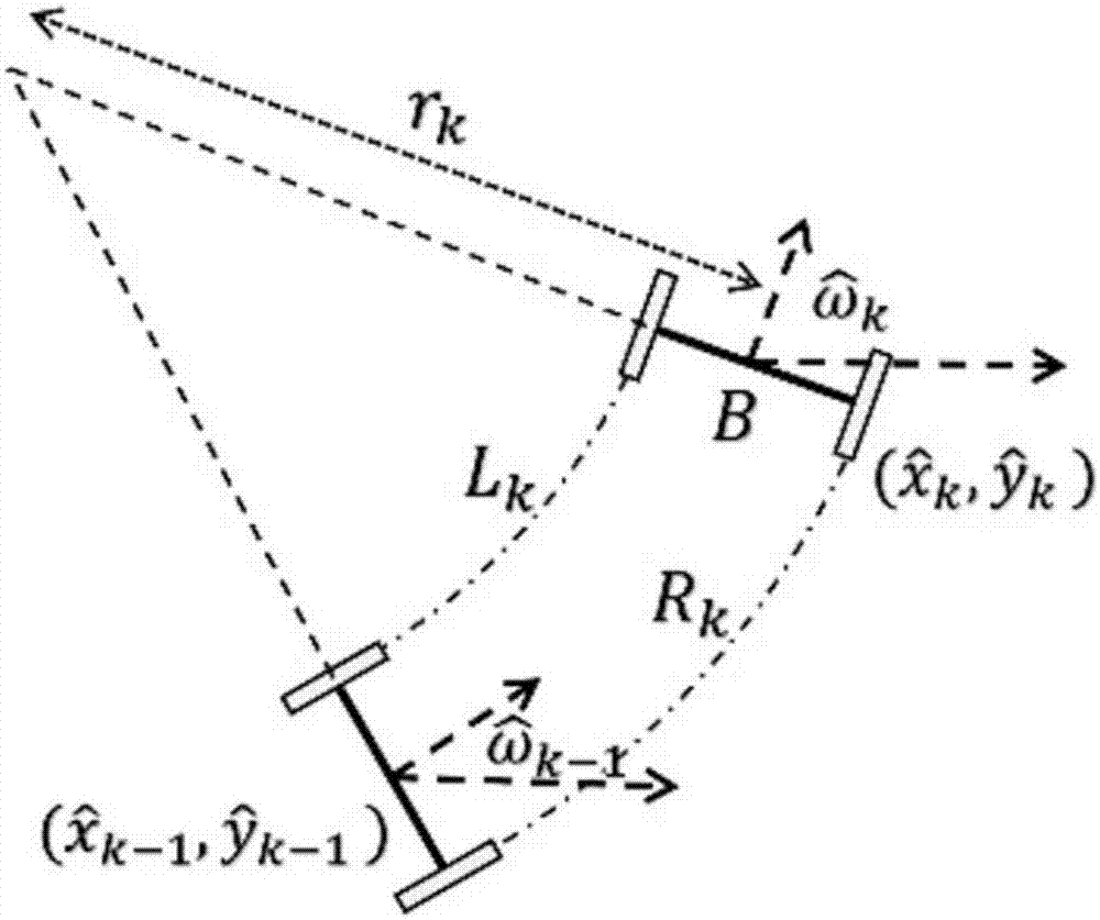
[0031] A): The robot is equipped with a laser sensor, a monocular camera, an RGB-D camera, a wheel odometer, an ultrasonic sensor, and an inertial measurement unit. The autonomous navigation system collects sensor information, and the wheel odometer module obtains a rough real-time attitude of the robot through dead reckoning. The two-wheel differential steering model is as follows: figure 1 As shown, the dead reckoning process of the two-wheel differential model is expressed as

[0032]

[0033]

[0034] where V k is the real-time motion rate of the robot; the visual odometer is based on the feature matching of the front and rear frames of stereo visio...

Embodiment 2

[0051] Embodiment 2. A method for automatic charging, positioning and navigation of a robot.

[0052] Step S1, continuously monitor the battery voltage, and when the voltage is lower than the threshold, use the method in Embodiment 1 to guide the robot to the front of the charging pile.

[0053] Step S2, collect the image through the image sensor, extract the visual sign placed on the charging pile in the image, set P i =[X i Y i Z i ] T , i=1,2,3,4 are the coordinates of the four vertices of the image logo in its own coordinate system, p i =[u i v i ] T , i = 1, 2, 3, 4 After image recognition, the four vertices of the image logo are corresponding points in the image, for P i The points are calculated through the pinhole camera model to obtain the image projection points, and the objective function is optimized After obtaining the transformation matrix of the robot relative to the image mark, the distance d=|t| between the robot and the image mark can be obtain...


PUM


Abstract

The invention discloses an autonomous navigation and automatic charging method for a service robot in a bank hall environment. The method comprises particular steps: when a robot needs to be deployed in a new bank hall, the robot is firstly remotely controlled to scan each area of the hall, a map is built, and task points are set according to business handling demands; in use, a navigation system guides the robot to a target point according to self positioning and a target task point position obtained through analysis by a bank business handling system. When the battery voltage of the robot is low, the navigation system firstly guides the robot near a charging pile, the robot is guided to be docked with the charging pile through a recognition marker, LED lamps at two sides of the marker are used as conditions for enabling the robot to stop moving, and automatic charging navigation is realized.

Description

technical field [0001] The invention belongs to the field of positioning and navigation of service robots, and relates to a method for autonomous navigation and automatic charging of a service robot for handling financial business in a bank hall environment. Background technique [0002] At present, banking business consultation and business processing are mainly handled manually, which is inefficient. At the same time, the bank's existing teller machines have complicated operation methods and cannot realize functions such as human-computer interaction. In addition, banking business promotion mainly relies on paper materials such as leaflets, resulting in waste of resources. The bank hall service robot can solve the above problems very well, and provide guidance services for customers who come to handle business, reduce the workload of bank guides, and has high application value. [0003] Autonomous navigation is a key technology of mobile robots, and it is also a key indi...

Claims


Application Information

Patent Timeline
IPC IPC(8): G05D1/02
CPCG05D1/0217G05D1/0234G05D1/0255G05D1/0257G05D1/027
Inventor 杨毅朱敏昭张鲁张凯宋文杰张炳华王健行
Owner BEIJING INSTITUTE OF TECHNOLOGYGY
Learn More