Power switch cabinet

A power switch and instrument technology, applied in substation/switch layout details, substation/switchgear cooling/ventilation, electrical components, etc. Good condition, reduce instrument line aging, easy installation

Inactive Publication Date: 2017-08-18
YANTAI POWER SUPPLY COMPANY OF STATE GRID SHANDONG ELECTRIC POWER +1
View PDF5 Cites 1 Cited by
  • Summary
  • Abstract
  • Description
  • Claims
  • Application Information

AI Technical Summary

Problems solved by technology

[0002] The switch cabinet where the power meter is installed is usually a closed box structure, which is not convenient for ventilation, which causes the instrument line in the box to be easily aged, which greatly increases the maintenance cost. At the same time, according to different installation locations, different types of meter boxes need to be used. Occasions are customized, and the production cost is also greatly increased

Method used


Image

  • Power switch cabinet
  • Power switch cabinet

Examples


Embodiment 1

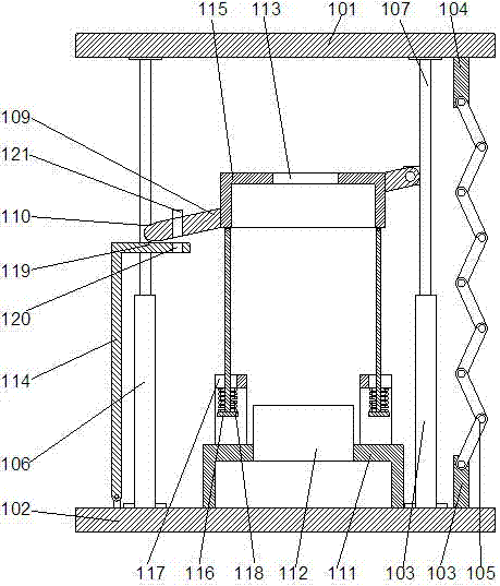
[0020] In this embodiment, in order to cover the terminals connecting the cables inside the cabinet when needed, preferably, a sealing plate 114 is provided on the side of the front support rod 106 away from the rear support rod 108, so that The lower end of the sealing plate is fixedly connected to the lower end cover, so that the upper end surface of the sealing plate 114 is attached to the lower end surface of the instrument support plate 109 . After connecting the instrument, make the sealing plate cover the outside of the bracket, use the sealing plate to wrap the bracket inside the cabinet, the bracket and the terminal cannot be seen directly from the outside, so that the cables connected to the instrument are covered inside the cabinet, Therefore, it is not easy to have the problem of illegally connecting cables and causing electricity theft.

[0021] In this embodiment, in order to fix the sealing plate conveniently, it is further preferred that the lower end of the se...

Embodiment 2

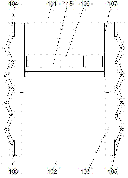
[0023] In this embodiment, in order to facilitate the installation of meter equipment, preferably, the instrument support plate 109 is provided with a boss 115 for installing the instrument. After the instrument support plate is fixed on the slot, the upper end surface of the boss Relatively parallel to the lower end surface, it is convenient to install the meter. A through hole for fixing the meter is provided on the boss 115. The meter can be fixed on the boss with bolts, so that the wire passing hole 113 is located on the boss. The middle part of Taiwan 115 is convenient for connecting cables.

[0024] Further preferably, in this embodiment, an inverted T-shaped connecting rod 116 is arranged below the boss 115, so that the upper end of the connecting rod 116 is hinged on the lower end surface of the boss 115, so that The connecting rod can rotate relative to the lower end surface of the boss, and a connecting plate 117 is arranged on the bracket 111, so that the connecting...


PUM


Abstract

The invention discloses a power switch cabinet, which comprises an upper end cover and a lower end cover, and is characterized in that the lower end cover is provided with supporting plates thereon, the lower end face of the upper end cover is provided with mounting plates which correspond to the supporting plates in position, each supporting plate is provided with foldable ventilating plate thereon, the end, which is away from the supporting plate, of the ventilating plate is hinged at the lower end face of the corresponding mounting plate, the lower end cover is provided with two front supporting rods and two rear supporting rods, the inner side of each front supporting rod and the inner side of each rear supporting rod are respectively provided with lifting rods, the upper end of each lifting rod is pressed against the lower end face of the upper end cover, and the rear supporting rods are provided with an instrument support plate thereon. The power switch cabinet can adjust the height of a box body when needed through matching the foldable ventilating plates with the liftable internal supporting rods and the lifting rod structure. In addition, the power switch cabinet has better ventilation effects.

Description

technical field [0001] The invention relates to a power switch cabinet. Background technique [0002] The switch cabinet where the power meter is installed is usually a closed box structure, which is not convenient for ventilation, which causes the instrument line in the box to be easily aged, which greatly increases the maintenance cost. At the same time, according to different installation locations, different types of meter boxes need to be used. Occasions are customized, and the production cost is also greatly increased. Contents of the invention [0003] The object of the present invention is to provide a kind of electric switchgear, by adopting foldable ventilating plate and the internal support rod and lifting rod structure that can be lifted, the height of the box body can be adjusted when needed, and it has better ventilation effect . [0004] The present invention is realized through the following technical solutions: [0005] A power switchgear, comprising an...

Claims


Application Information

Patent Timeline
Patent Type & Authority Applications(China)
IPC IPC(8): H02B1/56H02B1/30H02B1/32
CPCH02B1/565H02B1/30H02B1/32
Inventor 胡国伟周毅田书然郭松宇杨琳梁屿杨帆曲世凯
Owner YANTAI POWER SUPPLY COMPANY OF STATE GRID SHANDONG ELECTRIC POWER
Why Eureka
Try Eureka