
A Method of Flow Simulation in Complex Fractured Reservoirs

A complex fracture and flow simulation technology, applied in the direction of earthwork drilling and production, wellbore/well components, etc., can solve the problems of difficult to simulate multiphase flow, large gap between fracture grid and bedrock grid scale, and complex small-scale mapping relationship question

Active Publication Date: 2019-03-26
CHINA UNIV OF PETROLEUM (EAST CHINA)
View PDF7 Cites 0 Cited by
  • Summary
  • Abstract
  • Description
  • Claims
  • Application Information

AI Technical Summary

Problems solved by technology

[0003] However, based on the dual-media model, it is assumed that the fracture system is distributed in a uniform network, which cannot truly reflect the randomness and multi-scale nature of fractures, and is not suitable for fine flow simulation in fractured reservoirs. The theoretical basis of the equivalent continuum model is scale upgrading. Theory, in essence, is to reduce the order of the mathematical model. The upgraded large-scale model artificially smooths the strong heterogeneity and multi-scale of the medium, which is too macro-simplified and cannot capture the characteristics of small-scale flow.
The discrete fracture model displays and simulates each fracture with high calculation accuracy and good fidelity. However, the numerical simulation of discrete fracture flow based on traditional numerical methods is still difficult to apply in practice due to the large amount of calculation.
[0004] In order to reduce the amount of calculation, various ways to reduce the amount of calculation have also emerged. Among them, although the scaling method can reduce the amount of calculation, it cannot fully reflect the heterogeneity of the reservoir, and the calculation accuracy is not high
In recent years, multi-scale numerical methods have been gradually extended to the study of fractured reservoirs: Natvig et al. studied discrete fractured reservoirs based on the streamline simulation method combined with multi-scale simulation finite difference. In their study, fractures were viewed as For a high-permeability zone with a certain degree of opening, fine unstructured grid division is required; then, Gulbranse considered the influence of caves, and established a multi-scale mixed finite element single-phase flow numerical calculation format for fracture-cavity reservoirs. On a fine scale, multi-scale basis functions are constructed based on the Stokes–Brinkman flow equation, the Stokes equation is used in caves, and the Darcy equation is used in bedrock and fractures. However, it is difficult to determine the parameters of the transition region in the simulation, so it is difficult to simulate multiphase Flow; these two methods regard fractures as narrow and highly conductive channels, and require fine grid division for fractures. Due to the small size of fractures, the number of grids is large and the scale of fracture grids is different from that of bedrock grids. Large, resulting in cumbersome calculations
[0005] Subsequently, the multi-scale Galerkin finite element method of the discrete fracture model appeared, which reduced the dimension of the fracture and simplified the grid division process, but the multi-scale Galerkin finite element method has the disadvantage of local non-conservation. At the same time, Hajibeygi et al. proposed an iterative multi-scale finite volume method based on an embedded discrete fracture model. The discrete fracture model is directly embedded in the bedrock unit, which can avoid the complicated meshing process and further improve the calculation efficiency. However, the multi-scale is limited. The volumetric method needs to build a double grid system, and the small-scale mapping relationship is complex. These multi-scale numerical methods for fractured reservoirs cannot reflect the influence of microfractures on the flow, resulting in inconformity with the actual reservoir development

Method used


Image

  • A Method of Flow Simulation in Complex Fractured Reservoirs
  • A Method of Flow Simulation in Complex Fractured Reservoirs
  • A Method of Flow Simulation in Complex Fractured Reservoirs

Examples


Embodiment Construction

[0056] The purpose of the present invention is to provide a method for simulating the flow of complex fractured reservoirs.

[0057] In order to make the above objects, features and advantages of the present invention more comprehensible, the present invention will be further described in detail below in conjunction with the accompanying drawings and specific embodiments.

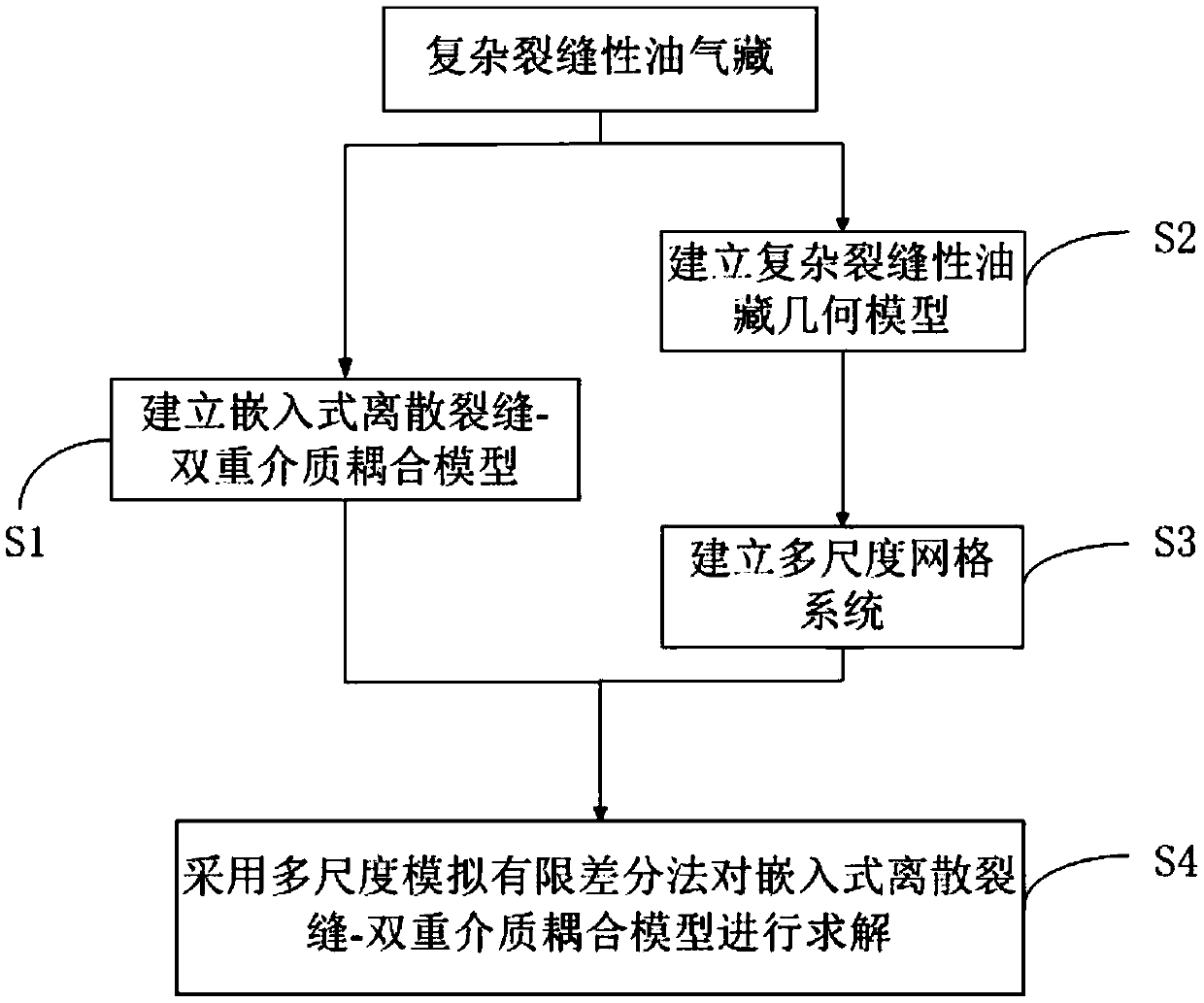
[0058] Such as figure 1 As shown, as an implementable method, a method for flow simulation of complex fractured reservoirs includes the following steps:

[0059] S1. Establish an embedded discrete fracture-dual medium coupling model according to the seepage characteristics of micro-fractures and large fractures;

[0060] S2. According to the actual geological data of fractured oil and gas reservoirs, determine the distribution of large fractures, hydraulic fractures and micro-fractures in the oil and gas reservoirs, and establish a geometric model of complex fractured reservoirs; Figure 4 As shown, the g...


PUM


Abstract

The invention discloses a method for simulating the flow of complex fractured oil reservoirs. The dual medium model is used to simulate micro-fractures, the embedded discrete fracture model is used to simulate large fractures, and the embedded discrete fracture is realized through the channeling function between large fractures and micro-fractures. The coupling between the fracture model and the dual-media model, an embedded discrete fracture-dual-media coupling model is established to simulate the flow of fractured reservoirs, which can accurately describe the fluid flow in fractures, and the embedded discrete The fracture-dual-medium coupling model is used to solve the problem, only macroscopic and large-scale calculations are required, and the fine flow characteristics of small-scale fractures are described through multi-scale basis functions, which greatly reduces the calculation amount and increases the calculation speed while ensuring the calculation accuracy. The simulation of fractured reservoir flow with high simulation accuracy and less calculation is carried out.

Description

technical field [0001] The invention relates to the field of flow simulation of fractured oil reservoirs, in particular to a method for flow simulation of complex fractured oil reservoirs. Background technique [0002] As the smallest geological structure, fractures are widely distributed in the earth's crust, and fractures of different sizes exist in almost all oil reservoirs. According to incomplete statistics, fractured oil reservoirs account for about half of the total proven reserves in the world; in my country, the proven geological reserves of fractured oil reservoirs account for more than 28% of the total proven reserves. The simulation of fractured reservoir flow has become an important way to explore reservoirs. At present, there are mainly three flow mathematical models based on dual media, equivalent continuous media and discrete fractures. The dual media model believes that there are two parallel seepage systems in the media. : The fracture system is the main f...

Claims


Application Information

Patent Timeline
Patent Type & Authority Patents(China)
IPC IPC(8): E21B49/00
CPCE21B49/00
Inventor 黄朝琴张庆福姚军黄涛张晓宇
Owner CHINA UNIV OF PETROLEUM (EAST CHINA)
Learn More