
Bridge equipment

A technology of equipment and bridges, which is applied in the field of bridge equipment, can solve the problems of being unable to change the area occupied by the covering device, changing the distance of the covering device according to needs, and inconvenient disassembly and assembly, so as to prevent the center of gravity from shifting and reduce direct exposure to the sun , uniform spray effect

Inactive Publication Date: 2017-08-04
陈光才
View PDF6 Cites 1 Cited by
  • Summary
  • Abstract
  • Description
  • Claims
  • Application Information

AI Technical Summary

Problems solved by technology

[0002] With the continuous improvement of people's living standards and the continuous increase of traffic, more and more traffic is driving on bridge roads, which requires traffic police to direct traffic. In hot summer or rainy days, traffic police need awnings or awnings when directing traffic Covering devices such as awnings are used to avoid heat and rain. The traditional covering device has a simple design and structure, which is inconvenient to disassemble and assemble, and the distance between the pillars of the covering device cannot be changed as required, nor can the occupied area of ​​the covering device be changed.

Method used


Image

  • Bridge equipment
  • Bridge equipment
  • Bridge equipment

Examples


Embodiment Construction

[0023] All features disclosed in this specification, or steps in all methods or processes disclosed, may be combined in any manner, except for mutually exclusive features and / or steps.

[0024] Any feature disclosed in this specification (including any appended claims, abstract and drawings), unless expressly stated otherwise, may be replaced by alternative features which are equivalent or serve a similar purpose. That is, unless expressly stated otherwise, each feature is one example only of a series of equivalent or similar features.

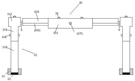
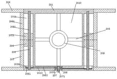
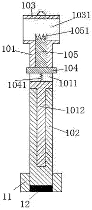
[0025] Such as Figure 1-6 As shown, a kind of bridge equipment of the present invention comprises top plate 20, pillar 10 and sunshade net 30, and described top plate 20 comprises main board body 201, and in described main board body 201, the left and right sides is symmetrically provided with the slide that stretches front and back and starts outwards. Move the slot 2011, the front end of the main board body 201 is provided with a midpoint ...


PUM


Abstract

The invention relates to bridge equipment which comprises a top plate, a supporting column and a sun-shading net. The top plate comprises a main plate body. Sliding grooves which extend front and back and are opened outward are symmetrically arranged in the main plate body left and right; a central point rotary chamber located at the center left and right is arranged on the front end of the main plate body, a first rotary wheel is rotatably mounted in the central point rotary chamber through a rotary rod; a side rotary chamber is arranged on the front end of the sliding groove; transfer grooves communicating each other are arranged between the side rotary chamber and the central point rotary chamber; a front slide block and a back slide block are slidably mounted in each of the sliding grooves front and back; a front screw rod and a back screw rod are spirally mounted in the front slide block and the back slide block in a matched manner, separately; the front screw rod and the back screw rod are fixedly connected; a second rotary wheel is mounted in the side rotary chamber; the second rotary wheel is fixedly connected to the front screw rod; rotary belts are mounted on the first rotary wheel and the second rotary wheel; and a front connecting rod which extends forward is fixedly arranged on the outer side end of the front slide block, and a back connecting rod which extends forward is fixedly arranged on the outer side end of the back slide block.

Description

technical field [0001] The invention relates to the field of bridges, in particular to bridge equipment. Background technique [0002] With the continuous improvement of people's living standards and the continuous increase of traffic, more and more traffic is driving on bridge roads, which requires traffic police to direct traffic. In hot summer or rainy days, traffic police need awnings or awnings when directing traffic Covering devices such as awnings are used to avoid heat and rain. The traditional covering devices have a simple design and structure, are inconvenient to disassemble, and cannot change the distance between the pillars of the covering device as required, neither can change the occupied area of ​​the covering device. Contents of the invention [0003] The object of the present invention is to provide a bridge device capable of overcoming the above-mentioned drawbacks of the prior art. [0004] According to the present invention, a kind of bridge equipment...

Claims


Application Information

Patent Timeline
Patent Type & Authority Applications(China)
IPC IPC(8): E04H1/12E04B1/343
CPCE04H1/1227E04B1/34305
Inventor 陈光才
Owner 陈光才
Learn More