Welding device

A technology for welding devices and welding components, applied in the direction of electric heating devices, auxiliary devices, welding equipment, etc., can solve problems such as difficulty in taking into account the fixation of welding parts, lower production efficiency and product qualification rate, and lack of rotary welding machines, etc., to achieve Improve welding efficiency and welding accuracy, simple structure effect

Inactive Publication Date: 2017-08-04
陈柯
View PDF7 Cites 0 Cited by
  • Summary
  • Abstract
  • Description
  • Claims
  • Application Information

AI Technical Summary

Problems solved by technology

[0002] In the process of welding circuit boards and other welding parts, it is difficult for workers to take into account the fixing of the welding parts, which leads to the displacement of the welding parts during the welding process and affects the welding. The clamping parts of some welding machines generally need to be manually fixed, which is time-consuming and laborious , and the fixing effect is not good, and it is easy to shift, which cannot effectively solve the problem of fixing the welded parts, which reduces the production efficiency and product qualification rate. In addition, the existing rotary welding machine does not have the function of immediately stopping the welding process. Security risks

Method used


Image

  • Welding device
  • Welding device
  • Welding device

Examples


Embodiment Construction

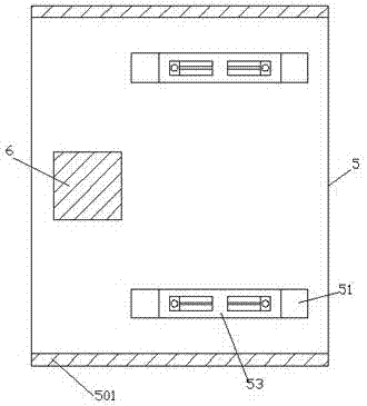
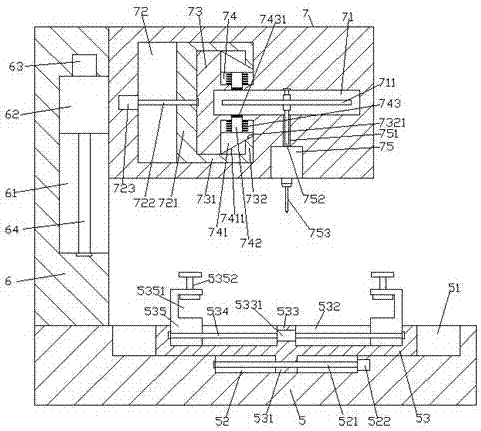
[0022] like Figure 1-Figure 5 As shown, a welding device of the present invention includes a base 5 and a welding assembly 7 arranged above the top of the base 5, a column 6 is provided on the top surface of the left side of the base 5, and the base 5 A first chute 51 is correspondingly arranged in the front and rear of the top surface of the left side, and a second chute 52 is arranged at the midpoint of the inner bottom surface of each of the first chute 51. The first screw rod 521, the first sliding block 53 is slidably connected in the first sliding groove 51, the welding assembly 7 is provided with a sliding cavity 72, and the right side of the sliding cavity 72 is provided with a bump 73 , the bump 73 is provided with a locking cavity 71 extending to the right side, the bottom surface of the welding assembly 7 is fixedly provided with a welding electric rotating machine 75, and the bottom of the welding electric rotating machine 75 is matched with a welding head 753. A...


PUM


Abstract

The invention discloses a welding device which comprises a base and a welding assembly arranged above the top of the base. A pillar is arranged on the top face of the left side of the base, and first sliding grooves are correspondingly formed in the top face of the left side of the base in a left-right manner. A second sliding groove is formed in the middle point of the inner bottom face of each first sliding groove. A first spiral rod extending left and right is arranged in each second sliding groove. A first sliding block is connected in each first sliding groove in a sliding fit manner. A sliding cavity is formed in the welding assembly. A protruding block is arranged in the right side of the sliding cavity, and a locking cavity extending towards the right side is formed in the protruding block. A welding electric rotating machine is fixedly arranged in the bottom face of the welding assembly, a welding head is cooperatively connected to the bottom of the welding electric rotating machine, an open groove is formed between the top of the welding electric rotating machine and the bottom of the locking cavity, and a shaft rod extending vertically is cooperatively connected in the open groove. The welding device is simple in structure, high in safety and capable of improving the welding efficiency and the welding accuracy.

Description

technical field [0001] The invention relates to the field of welding, in particular to a welding device. Background technique [0002] In the process of welding the welding parts such as circuit boards, it is difficult for workers to take into account the fixing of the welding parts, which leads to the displacement of the welding parts during the welding process, which affects the welding. The clamping parts of some welding machines generally need to be manually fixed manually, which is time-consuming and labor-intensive. , and the fixing effect is not good, it is prone to offset, cannot effectively solve the problem of fixing the welding parts, and reduces the production efficiency and product qualification rate. In addition, the existing rotary welding machine does not have the function of immediately stopping the welding process. Security risks. SUMMARY OF THE INVENTION [0003] The technical problem to be solved by the present invention is to provide a welding device ...

Claims


Application Information

Patent Timeline
IPC IPC(8): B23K3/00B23K3/04B23K37/02B23K3/08B23K101/42
CPCB23K37/0252B23K3/00B23K3/04B23K3/087B23K2101/42
Inventor 陈柯
Owner 陈柯
Why Eureka
Try Eureka