Solenoid

A solenoid and coil technology, applied to electromagnets, valve details, electrical components, etc., can solve the problems of increased material costs and manufacturing costs, increased weight of movable parts, and increased axial length, etc., to achieve the suppression of material costs , Responsive deterioration is suppressed, and assembly property is good

Active Publication Date: 2017-08-01
EAGLE INDS
View PDF9 Cites 0 Cited by
  • Summary
  • Abstract
  • Description
  • Claims
  • Application Information

AI Technical Summary

Problems solved by technology

[0015] However, in Conventional Technology 2, it is necessary to increase the axial lengths of both the movable stator core and the second stator core in pairs, which increases material and manufacturing costs.
In addition, since the entirety of the movable element core is increased, there is also a problem that the weight of the movable part increases and the responsiveness deteriorates.

Method used


Image

  • Solenoid
  • Solenoid
  • Solenoid

Examples


Embodiment 1

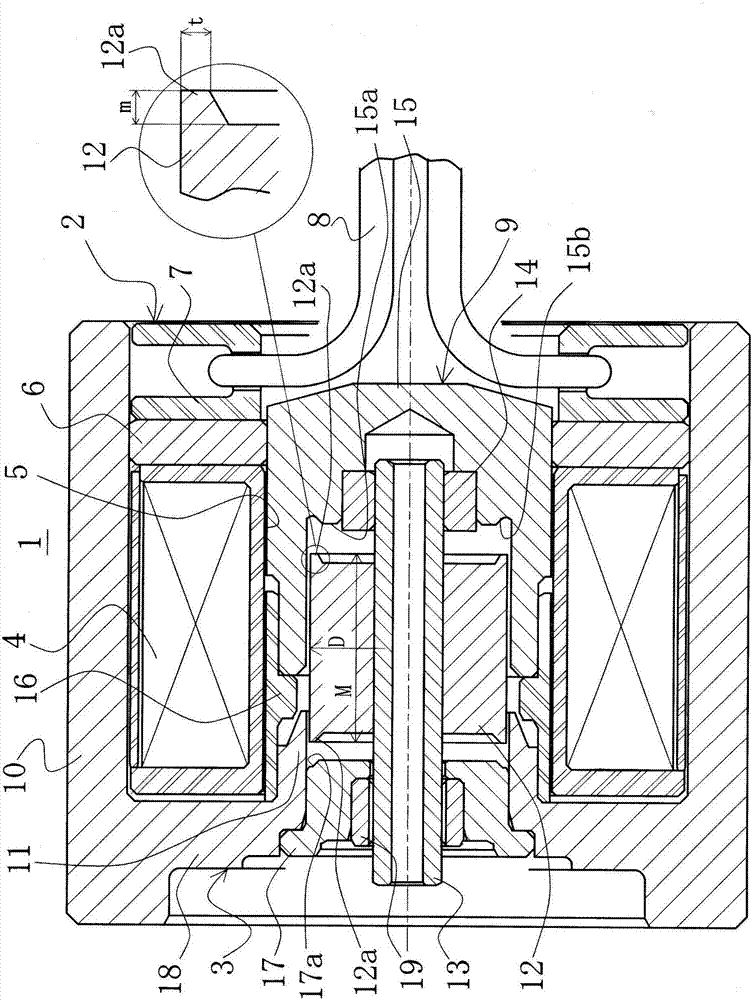
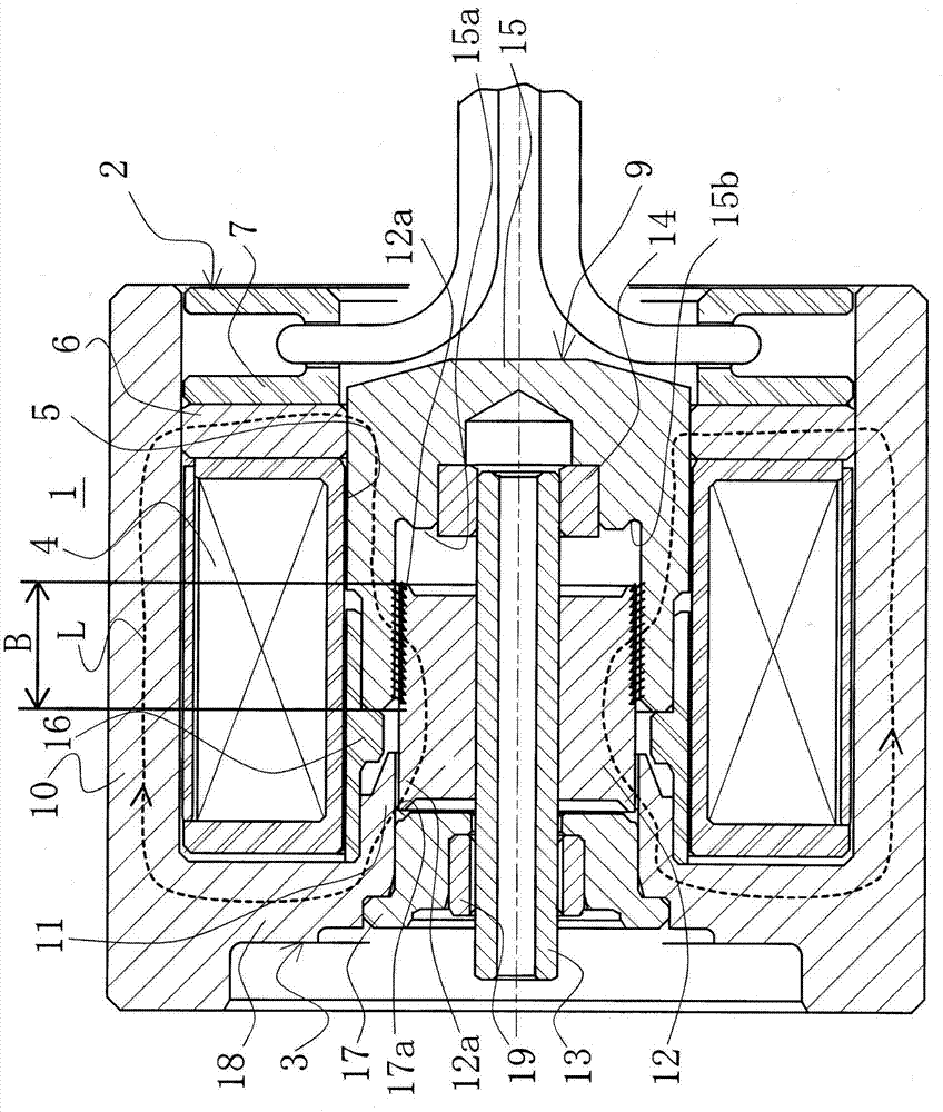
[0050] refer to figure 1 and figure 2 , the solenoid of Embodiment 1 of the present invention will be described.

[0051] The solenoid 1 is configured by integrating a molded coil 2 and a solenoid body 3 .

[0052] The molded coil 2 is wound with a coil 4, and a hole 5 recessed toward the solenoid main body 3 side is formed at the center of the coil 4. As shown in FIG.

[0053] In addition, on the side opposite to the solenoid main body 3 of the molded coil 2, an annular plate 6 is provided adjacent to the coil 4, and a molded portion 7 forming the bottom surface of the hole 5 is provided in front of the plate 6. . Inside the mold portion 7 , the coil wire drawn out from the coil 4 is connected to a lead wire 8 . The plate 6 is formed of a magnetic material.

[0054] On the other hand, the solenoid main body 3 is provided with: a column part 9 inserted into the hole 5 of the molded coil 2 at the axial center; A case 10 covering the outer periphery of the molded coil 2 ...


PUM


Abstract

Provided is a solenoid exhibiting flat characteristics without an increase in the physical constitution (size) of the solenoid. The solenoid (1) is provided with: a mold coil (2) having a hole (5) at the center of a coil (3) wound a plurality of times; a solenoid body (3) including a case (10) covering the outer periphery of the mold coil (2), a movable plunger (12) inserted in the hole (5) at the center of the mold coil (2), and a magnetic suction portion (11) disposed in a direction toward which the plunger (12) is moved and suctioned by a magnetic force generated by the coil (3); a ring-shaped plate (6) disposed on the opposite side of the mold coil (2) from the solenoid body (3) and adjacent to the coil (3); and a sleeve (15) facing the magnetic suction portion (11) with the interposition of an air gap and supporting one side of a rod (13) connected to the plunger (12), wherein a magnetic circuit (L) is formed, the magnetic circuit (L) passing through the magnetic suction portion (11), the case (10), the sleeve (15), the plunger (12), and returning to the magnetic suction portion (11), characterized in that the plunger (12) has an outer edge extension portion (12a) formed by an axial extension of an outer edge portion of the plunger.

Description

technical field [0001] The present invention relates to solenoids used for solenoid valves and the like for various oil and gas control equipment such as shock absorbers, for example. Background technique [0002] Currently, as such a solenoid, for example, has Figure 4 and Figure 5 The solenoid shown. [0003] The solenoid 50 is configured by integrating a molded coil 51 and a solenoid body 52 into one. [0004] The molded coil 51 is wound with a coil 53 , and a hole 54 recessed toward the solenoid main body 52 side is formed at the center of the coil 53 . [0005] In addition, an annular plate 55 is provided adjacent to the coil 53 on the side opposite to the solenoid main body 52 of the molded coil 51 , and a molded portion 56 forming the bottom surface of the hole 54 is provided in front of the plate 55 . , inside the molding part 56 , the coil wire drawn from the coil 53 is connected to the lead wire 57 . [0006] On the other hand, the solenoid main body 52 is pr...

Claims


Application Information

Patent Timeline
Patent Type & Authority Applications(China)
IPC IPC(8): H01F7/16F16K31/06
CPCF16K31/0675H01F7/1607H01F2007/085H01F2007/086
Inventor 福永秀二
Owner EAGLE INDS
Why Eureka
Try Eureka