
Coverless clutch with hollow pin and centering aid

A clutch and configuration technology, applied in the field of clutches, can solve problems such as defective assembly and difficult assembly, and achieve the effect of simple configuration

Active Publication Date: 2019-03-12
SCHAEFFLER TECH AG & CO KG
View PDF8 Cites 0 Cited by
  • Summary
  • Abstract
  • Description
  • Claims
  • Application Information

AI Technical Summary

Problems solved by technology

As a result, assembly can only be carried out within a predetermined time window with great difficulty, since the individual support pins must be mounted fixed in a fixed position provided against the pressure plate / flywheel
There is also the risk that a defective assembly may occur where high inherent stresses are introduced

Method used


Image

  • Coverless clutch with hollow pin and centering aid
  • Coverless clutch with hollow pin and centering aid

Examples


Embodiment Construction

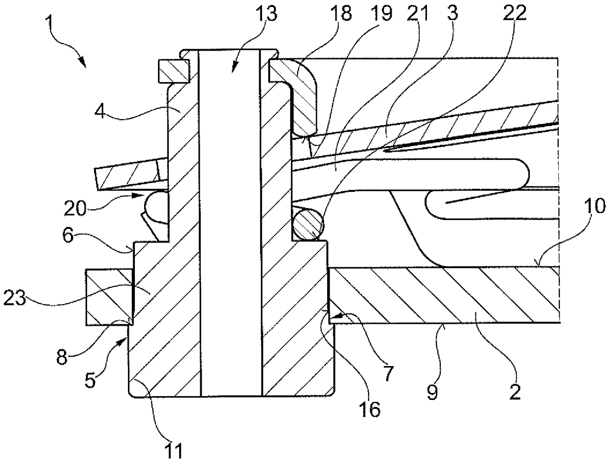
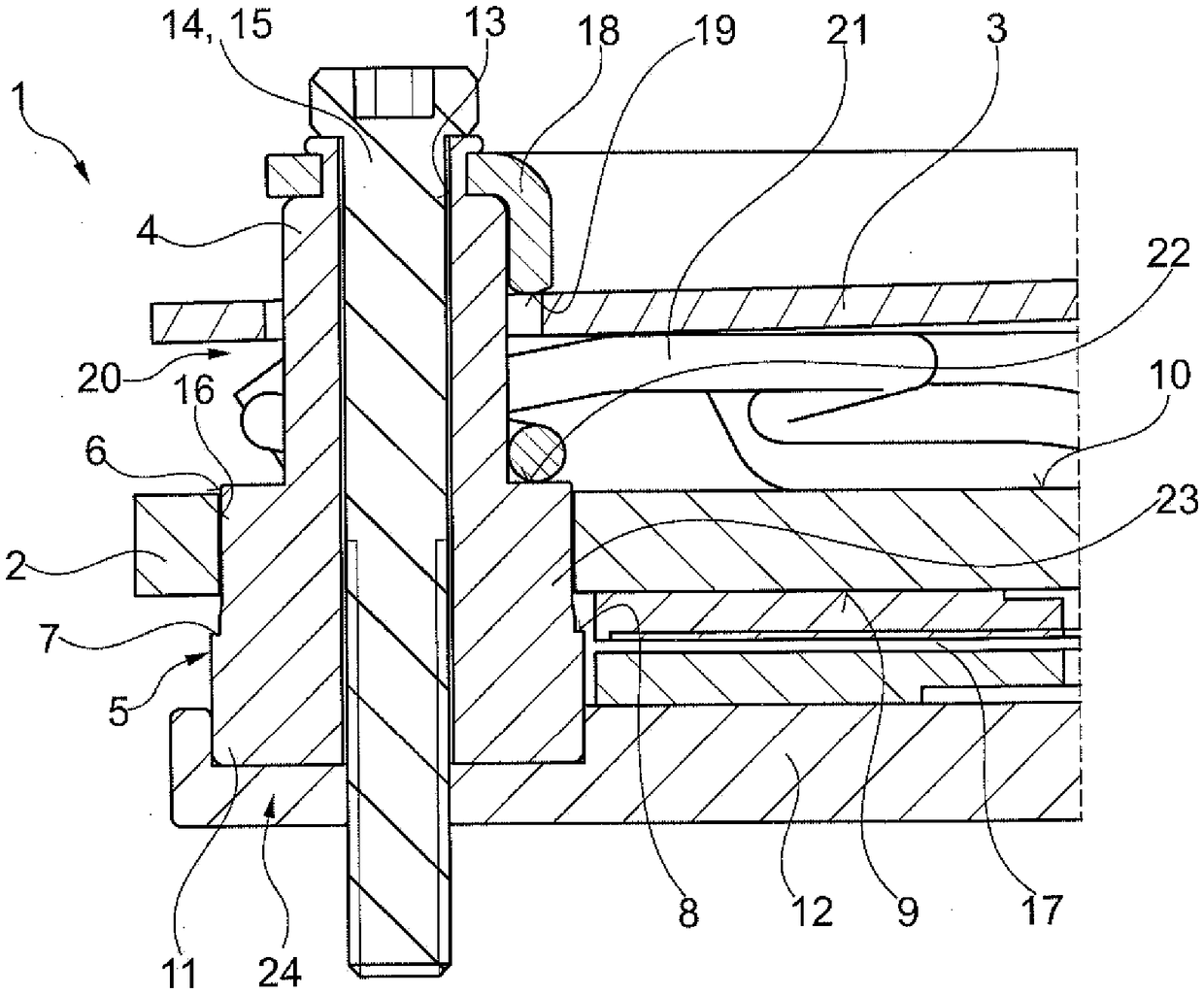
[0026] exist figure 1 The clutch 1 according to the invention according to an advantageous first embodiment can be clearly seen in the figure. The clutch 1 is designed as a friction clutch / friction clutch, ie a dry-running friction clutch, however, alternatively, the friction clutch is also designed to run wet. In the operating state / during operation, the clutch 1 is integrated into the drive train of the motor vehicle, which is not further illustrated here for reasons of clarity. In this case, the clutch 1 is usually mounted as a disengageable clutch element between the output shaft (crankshaft) of an internal combustion engine, such as a diesel or gasoline engine, of a motor vehicle and a transmission input shaft of a transmission.

[0027] The clutch 1 according to the depicted, preferred first embodiment is provided for, as follows with figure 2 Interconnected and explanatory, it is mounted directly on the counter-pressure plate 12 configured as a flywheel. In the usua...


PUM


Abstract

The invention relates to a clutch (1) for a drive train of a motor vehicle, comprising a pressure plate (2), which is supported in such a way that the pressure plate can be moved between an engaged position and a disengaged position, and a lever element (3), which is supported on a pivot support formed by a plurality of supporting pins (4) in such a way that the lever element can be pivoted in relation to the pressure plate (2), wherein the position of the pressure plate (2) depends on a pivoting position of the lever element (3), wherein each supporting pin (4) has a centering segment (5), which centering segment (5) lies against the pressure plate (2) in a transport state of the clutch (1) in such a way that the centering segment centers the supporting pin (4) in relation to the pressure plate (2).

Description

technical field [0001] The present invention relates to a clutch (preferably a friction / friction clutch) for the drive train of a motor vehicle, such as a passenger car, truck, bus or agricultural commercial vehicle, said clutch having a Adjustably mounted (preferably axially displaceable) pressure plate and a lever element, which is pivotally supported relative to the pressure plate on a pivot bearing structure formed by a plurality of support pins, wherein , the position of the pressing plate depends on the swing position of the lever element. [0002] Here, the clutch is preferably designed as a coverless clutch, ie a clutch cover is omitted in this clutch design. Background technique [0003] Such clutches are already known from the prior art, wherein, for example, the applicant has known an internal prior art which has not yet been published but has been filed as a German patent application at the German Patent and Trademark Office with the document number 102014 211 ...

Claims


Application Information

Patent Timeline
Patent Type & Authority Patents(China)
IPC IPC(8): F16D13/58
CPCF16D13/585F16D2013/581
Inventor C·拉贝尔M·法尔克
Owner SCHAEFFLER TECH AG & CO KG
Learn More