Liftable cleaning type dyeing equipment

A technology of dyeing equipment and supporting components, which is applied in the direction of textile material cleaning device, spray/jet textile material treatment, etc. It can solve the problems of poor dyeing quality, inconvenient disassembly of dyeing equipment, and difficulty in quick disassembly, quick positioning and fixing, etc. , to achieve the effect of easy operation, simple and ingenious structure

Inactive Publication Date: 2017-07-25
CHANGXING JIAPU YIHANG TEXTILE FACTORY
View PDF1 Cites 3 Cited by
  • Summary
  • Abstract
  • Description
  • Claims
  • Application Information

AI Technical Summary

Problems solved by technology

[0006] The purpose of the present invention is to overcome the disadvantages of the prior art, to overcome the inconvenient disassembly of dyeing equipment, it is difficult to realize rapid disassembly and fast positioning and fixing, and the problems of poor dyeing quality due to long-term non-cleaning

Method used


Image

  • Liftable cleaning type dyeing equipment
  • Liftable cleaning type dyeing equipment
  • Liftable cleaning type dyeing equipment

Examples


Embodiment 1

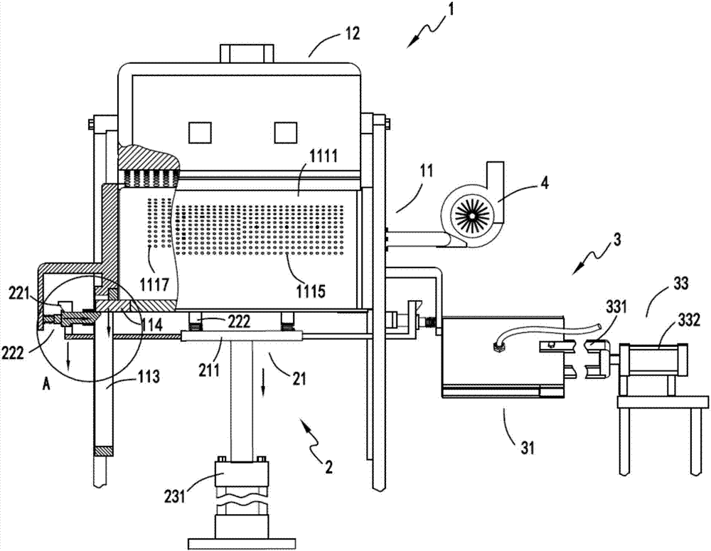
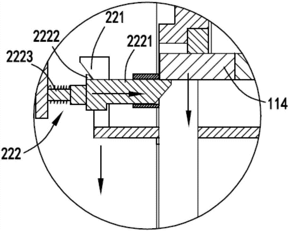
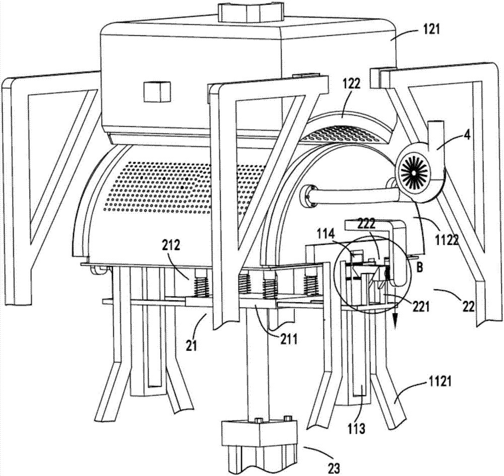
[0046] figure 1 It is a schematic diagram of the front view of the lifting and cleaning dyeing equipment, figure 2 Schematic diagram of the enlarged structure of the locking assembly, image 3 It is a schematic diagram of the structure when the supporting component is lowered, Figure 4 Schematic diagram of the enlarged structure of the locking assembly when the supporting assembly is lowered, Figure 5 It is a schematic diagram of the structure when the supporting component rises, Image 6 Schematic diagram of the enlarged structure of the locking assembly when the support assembly is raised, Figure 7 It is a schematic diagram of the structure of the scrubbing assembly, Figure 8 Schematic diagram of the structure of the auxiliary mechanism, Figure 9 is a schematic diagram of the structure of the slider unit, Figure 10 is a schematic diagram of the structure of the conduction device, Figure 11 is a schematic diagram of the cloth passing through the support component...

Embodiment 2

[0065] Such as figure 1 , figure 2 , image 3 , Figure 4 , Figure 5 , Image 6 , Figure 7 , Figure 8 , Figure 9 , Figure 10 , Figure 11 with Figure 12 As shown, the components that are the same as or corresponding to those in the first embodiment are marked with the corresponding reference numerals in the first embodiment. For the sake of simplicity, only the differences from the first embodiment will be described below. The difference between the second embodiment and the first embodiment is that the outer port of the wrinkle removal hole 1115 on the left side is inclined toward the center position on the arc surface corresponding to the negative pressure chamber a1114 with the center position as the dividing line, and the outer port on the right side is inclined towards the center position. The outer port of the corrugation hole 1115 is also inclined towards the center position.

[0066] The negative pressure chamber a1114 and the wrinkle removal hole 111...


PUM


Abstract

The invention relates to a lifting and cleaning type dyeing equipment, comprising a dyeing part, the dyeing part includes an auxiliary mechanism and a dyeing device; the auxiliary mechanism includes a support assembly and a sealing support assembly; The support part includes a load-bearing component, a locking component and a power component. The load-bearing component is driven by the power component to carry the support component for lifting movement. When the support component rises to dock with the sealing support component, the power component synchronously drives the locking component to lock the support component; The scrubbing part, the scrubbing part is arranged on one side of the lifting support part, the scrubbing part includes a scrubbing component a, a scrubbing component b and a push-pull component, the scrubbing component a and the scrubbing component b are driven by the push-pull component to clean the support component; overcome the dyeing equipment It is inconvenient to disassemble, and it is difficult to achieve rapid disassembly and fast positioning and fixing. If it is not cleaned for a long time, the dyeing quality will be poor.

Description

technical field [0001] The invention relates to the technical field of printing and dyeing equipment, in particular to a lifting and cleaning type dyeing equipment. Background technique [0002] There are generally two types of fabric dyeing techniques, painting and dip-dyeing. Exhaust dyeing method pollutes a lot and wastes materials. For painting and dyeing, the existing painting and dyeing equipment has the problems of inconvenient disassembly, difficult cleaning, uneven dyeing and incomplete absorption of dye by the cloth. [0003] A Chinese utility model patent with the authorized announcement number CN203782393U discloses a high-efficiency small bath ratio open-width spray dyeing machine. Water-based; however, the device has the following problems: [0004] 1. The equipment does not have the function of flexible disassembly, it is inconvenient to clean, and the long-term use of dirt will affect the quality of dyeing. [0005] 2. There are wrinkles in the process of ...

Claims


Application Information

Patent Timeline
Patent Type & Authority Applications(China)
IPC IPC(8): D06B1/02D06B23/30
CPCD06B1/02D06B23/30
Inventor 嵅奇
Owner CHANGXING JIAPU YIHANG TEXTILE FACTORY
Why Eureka
Try Eureka