


Quick Research
Generate reliable direction feasibility study reports for your R&D in just a few steps.

Technical Q&A
Discover and master advanced knowledge NOW. Basics, ideas, possibilities, all at once.

Find Solutions
As an expert in R&D theories, this can generate solutions to your technical problems instantly.

Evaluate Feasibility
Analyze your overall solution with one click, know your potential R&D risks in advance.

Monitor Landscape
Get weekly tech updates, stay abreast of the latest tech innovations and key insights.
Modeling method of hybrid logic dynamic model-based brushless direct-current motor driving system
A hybrid logic dynamic, brushed DC motor technology, applied in the direction of AC motor control, control system, AC power input conversion to DC power output, etc., can solve the problems of important information loss, no description of condition changes, unfavorable power tube analysis, etc. Achieve the effect of avoiding loss, improving real-time and reliability
- Summary
- Abstract
- Description
- Claims
- Application Information
AI Technical Summary
Benefits of technology
Problems solved by technology
Method used
Image


Examples
Embodiment Construction
[0019] The invention will be further described below with reference to the accompanying drawings and in combination with specific embodiments, so that those skilled in the art can implement it by referring to the description, and the protection scope of the present invention is not limited to the specific embodiments.
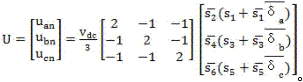
[0020] The technical solution adopted in the present invention is a modeling method for a brushless DC motor drive system based on a hybrid logic dynamic model, the brushless DC motor drive system includes a power supply, a brushless DC motor, a sensor, and a controller, and the brushless DC motor drive system includes a power supply, a brushless DC motor, a sensor, and a controller. The DC motor is composed of a constant voltage source, a motor body and a three-phase full-bridge inverter. The motor body includes three-phase symmetrical star windings and three opposite electromotive forces. The three-phase full-bridge inverter consists of six power Three half-br...
PUM
 Abstract
Description
Claims
Application Information
 - R&D Engineer
- R&D Manager
- IP Professional
- Industry Leading Data Capabilities
- Powerful AI technology
- Patent DNA Extraction
Browse by: Latest US Patents, China's latest patents, Technical Efficacy Thesaurus, Application Domain, Technology Topic, Popular Technical Reports.
© 2024 PatSnap. All rights reserved.Legal|Privacy policy|Modern Slavery Act Transparency Statement|Sitemap|About US| Contact US: help@patsnap.com