ladder layer cage
A stepped, laying hen technology, applied in poultry cages or houses, poultry industry, applications, etc., can solve the problems of manure removal, low degree of automation, large breeding area, etc., and improve the environment and structure of chicken houses. Simple and reliable, high stocking density results
- Summary
- Abstract
- Description
- Claims
- Application Information
AI Technical Summary
Problems solved by technology
Method used
Image
Examples
Embodiment 1
[0029] A ladder-type laying hen cage, including a controller, a main body of a laying hen cage, a feeding device, an egg picking device, a drinking device and a manure cleaning device. The main body of a laying hen cage includes a chicken cage frame 1 and a chicken cage body 2, and the chicken cage frame 1 is a trapezoidal frame, and there are more than four chicken cage bodies 2, which are symmetrically arranged on both sides of the chicken cage frame 1 to form a trapezoidal structure. An egg tray 3 is arranged under each chicken cage body 2, and the outside of each chicken cage body Both are equipped with a food trough 4, the feeding device is set above the food trough 4, the egg picking device is set on the side of the main body of the laying hen cage and connected with the egg tray 3, the drinking water device is set in the chicken cage body 2, and the excrement cleaning device is set Below the main body of the layer cage.
[0030] The laying hen cage in this embodiment ha...
Embodiment 2
[0032] Optimizing on the basis of Example 1, such as figure 1 As shown, the feeding device includes a conveying pipeline 41, a feed box 42, and a feeding port 43. One end of the conveying pipeline 41 is connected to a storage tank 44, and the other end of the conveying pipeline 41 is connected to a conveying power unit. There are more than two discharge openings 45, the feed box 42 has more than two and is respectively located below the two or more discharge openings 45, and the feed opening 43 has more than two and is arranged on the lower side of the feed box 42 at intervals. Each feeding port 43 is connected with a feeding pipeline 46, and the lower end of the feeding pipeline 46 is positioned in the corresponding trough 4.
[0033] The feeding device also includes a support fixed frame 47 for supporting the material box 42 , a vertical support rod 48 is arranged below the support fixed frame 47 , and a roller 49 is provided at the bottom of the vertical support rod 48 .
[...
Embodiment 3
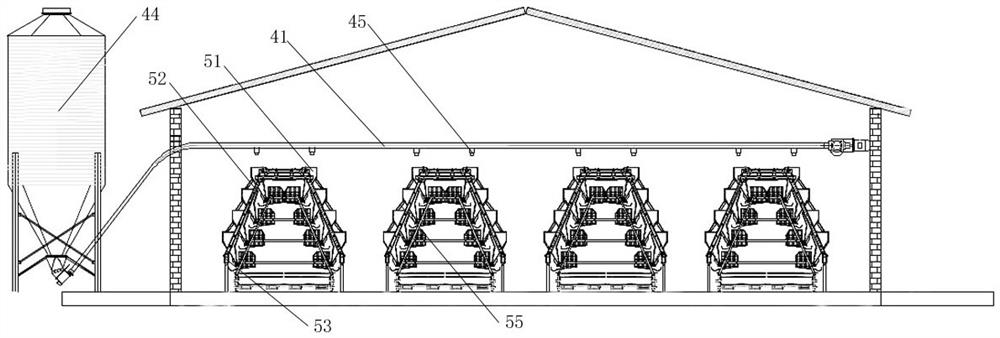
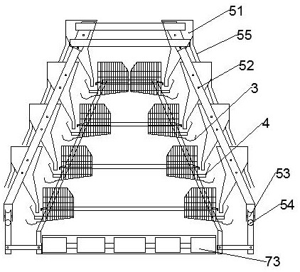
[0036] Optimizing on the basis of Example 1, such as figure 2 , 3 As shown, the feeding device includes a conveying pipeline 41 and a feeding box 51 and a feeding box support 52 arranged below the conveying pipeline 41. One end of the conveying pipeline 41 is connected to the storage tank 44, and the other end of the conveying pipeline 41 is connected to the conveying power unit. , the conveying pipeline 41 is provided with more than two discharge ports 45, and the feeding box 51 has more than four and is arranged successively above the food trough 4 of each chicken cage body 2, and the feeding of the uppermost layer of the laying hen cage body Below the discharge port 45 corresponding to the box 51 respectively, the feeding box bracket 52 fixes more than four feeding boxes 51 as a whole, and the lowest end of the feeding box 51 is provided with a second roller 53, and the second roller 53 A sliding shaft 54 for supporting the sliding of the second roller 53 is arranged be...
PUM
 Abstract
Description
Claims
Application Information
 - R&D
- Intellectual Property
- Life Sciences
- Materials
- Tech Scout
- Unparalleled Data Quality
- Higher Quality Content
- 60% Fewer Hallucinations
Browse by: Latest US Patents, China's latest patents, Technical Efficacy Thesaurus, Application Domain, Technology Topic, Popular Technical Reports.
© 2025 PatSnap. All rights reserved.Legal|Privacy policy|Modern Slavery Act Transparency Statement|Sitemap|About US| Contact US: help@patsnap.com


