
Oven with high working efficiency

A work efficiency, drying oven technology, applied in drying, drying machine, drying machine for static materials, etc., can solve the problems of air tightness defect of the drying oven, increase production cost, poor drying effect, etc., and reduce drying Time, cost saving, fast drying effect

Inactive Publication Date: 2017-06-30
全南县智护力工业产品设计有限公司
View PDF0 Cites 0 Cited by
  • Summary
  • Abstract
  • Description
  • Claims
  • Application Information

AI Technical Summary

Benefits of technology

This patented technology allows for efficient use of space while still allowing for quicker and easier opening or closure of boxes during dry cleanings without wasting excessive power from an external source like electricity. It achieves this by utilizing both internal and outer walls of the container instead of just making them up entirely. Additionally, there're also included features such as lamps attached at certain points along its length to improve visibility when navigating within the interior of the chamber. Overall, these improvements make the process safer and better overall performance compared to current methods.

Problems solved by technology

This patented technical problem addressed in this patents relates to existing conventional vacuums that have drawbacks such as requiring manual loading/unloading due to their lack of sealed design, difficulty accessing certain areas within them when needed, insensitive interior designs leading to low productivity rates, high power consumption, and excessively long cycle times.

Method used


Image

  • Oven with high working efficiency
  • Oven with high working efficiency
  • Oven with high working efficiency

Examples


Embodiment Construction

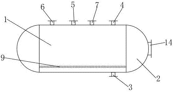
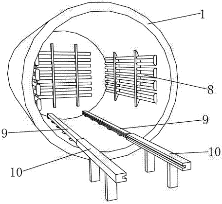
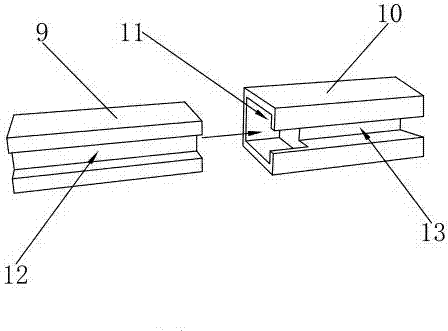
[0018] Such as Figure 1 to Figure 3 As shown, it is a high-efficiency oven of the present invention, including a box body 1, and one side of the box body 1 is rotatably connected with a box door 2, and the box door 2 is provided with a handle 14, which is convenient for opening and closing the box door 2. The other side of the body 1 is sealed and welded firmly, forming an elliptical double-head structure as a whole, which is closed in both directions and has good airtightness. The bottom of the box body 1 is provided with a sewage outlet 3, and the top of the box body 1 is respectively provided with a vent port 4, a vacuum port 5, a pressure measurement port 6 and a temperature measurement port 7. The sewage outlet 3 is used to discharge the waste generated during the drying process. For waste liquid, the vent port 4 is used to discharge gas to ensure a constant pressure in the box body 1 and avoid overpressure. The vacuum port 5 is used to evacuate the non-condensable gas ...


PUM


Abstract

The invention discloses an oven with high working efficiency, which comprises a box body, one side of the box body is rotatably connected with a box door, the inner side of the box body is provided with heating tubes, the inner side of the box body is fixed with a first track, the first track A second track is connected, and the second track is located outside the box. The bottom of the box is provided with a sewage outlet, and the top of the box is respectively provided with a vent port and a vacuum port. The invention has a double-head structure, good drying effect, fast drying speed, greatly reduced drying time, improved work efficiency, economy and energy saving, simple structure and low manufacturing cost.

Description


Claims


Application Information

Patent Timeline
Owner 全南县智护力工业产品设计有限公司
Learn More