Jack-up transfer machine and working method thereof as well as automated conveying line
A technology of jacking, transferring and working methods, which is applied in the direction of conveyors, conveyor objects, transportation and packaging, etc., and can solve the problems of rare transfer machines
- Summary
- Abstract
- Description
- Claims
- Application Information
AI Technical Summary
Problems solved by technology
Method used
Image


Examples
Embodiment 1
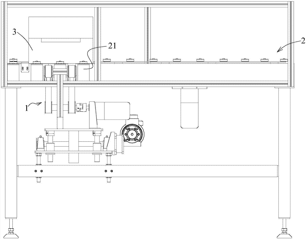
[0028] Such as Figure 1 to Figure 4 As shown, this embodiment 1 provides a single-bowl jacking transfer machine 1, including: a conveying mechanism 11 arranged orthogonal to the conveying direction of the conveying line 2; and a jacking mechanism 12 that lifts the conveying mechanism 11.
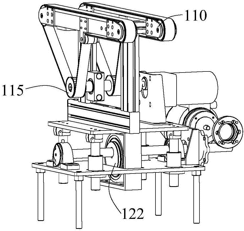
[0029] The conveying mechanism 11 includes: two timing belt rotating mechanisms 110, the two timing belt rotating mechanisms 110 are simultaneously raised or lowered from the corresponding rollers 21 of the conveying mechanism 11 through the jacking mechanism 12, and the timing belt rotating mechanism 110 is from the conveying line 2 is extended on one side; after being lifted, the two synchronous belt rotating mechanisms 110 are driven by a synchronous belt rotating motor 111 to rotate the synchronous belt 112. Specifically, the synchronous belt rotating motor 111 drives the synchronous belt wheel 115 through a coupling 113 Rotate.
[0030] The timing belt rotation mechanism 110 extends from o...
Embodiment 2
[0034] Such as Figure 1 to Figure 4 As shown, on the basis of Embodiment 1, this Embodiment 2 provides a conveying line 2 equipped with the single-bowl jacking transfer machine as described in Embodiment 1.
[0035] The transfer position of the conveying line 2 is provided with a photoelectric switch, and the photoelectric switch is connected with a control module; and the single pot jacking transfer machine is located directly below the transfer position; when the saggar 3 is transported to the transfer position After the position, the photoelectric switch is triggered. After the control module controls the lifting mechanism 12 to drive the conveying mechanism 11 to lift, the control module controls the conveying mechanism 11 to move the sagger 3 out; when the photoelectric switch detects that the saggar 3 is moved out , The control module controls the conveying mechanism 11 to stop, and controls the jacking mechanism 12 to descend and reset.
[0036] If the saggar 3 is sent bac...
Embodiment 3
[0039] On the basis of embodiment 1, this embodiment 3 provides a working method of a single bowl jacking transfer machine.
[0040] The working method of the single-bowl jacking transfer machine includes: after the sagger 3 is lifted from the conveying line 2 by the jacking mechanism 12, the conveying mechanism 11 is activated to transfer it out of the conveying line 2, and the saggar 3 is completed. Transfer; or start the lifting mechanism 12 to lift the conveying mechanism 11, and start the conveying mechanism 11
[0041] After the sagger 3 is sent directly above the conveying line 2, the conveying mechanism 11 is controlled to stop; then, the lifting mechanism 12 is controlled to lower and reset, so that the sagger 3 is fed into the conveying line 2.
[0042] The conveying mechanism 11 includes: two timing belt rotating mechanisms 110, the two timing belt rotating mechanisms 110 are simultaneously raised or lowered from the corresponding rollers 21 of the conveying mechanism 11 t...
PUM
 Abstract
Description
Claims
Application Information
 - R&D
- Intellectual Property
- Life Sciences
- Materials
- Tech Scout
- Unparalleled Data Quality
- Higher Quality Content
- 60% Fewer Hallucinations
Browse by: Latest US Patents, China's latest patents, Technical Efficacy Thesaurus, Application Domain, Technology Topic, Popular Technical Reports.
© 2025 PatSnap. All rights reserved.Legal|Privacy policy|Modern Slavery Act Transparency Statement|Sitemap|About US| Contact US: help@patsnap.com