
An inspection robot mechanism

A technology of inspection robot and walking mechanism, applied in the direction of overhead line/cable equipment, etc., can solve the problems of complex structure, heavy weight, low efficiency, etc., and achieve the effects of good safety protection, fast obstacle surmounting process, and wide application range

Active Publication Date: 2018-05-18
SHENYANG INST OF AUTOMATION - CHINESE ACAD OF SCI
View PDF6 Cites 0 Cited by
  • Summary
  • Abstract
  • Description
  • Claims
  • Application Information

AI Technical Summary

Problems solved by technology

Among them, the efficiency of manual inspection is low, the labor intensity is high, and the risk is high; the cost of helicopter inspection is expensive, and the quality of inspection is easily affected by the climate
International research on transmission line inspection robot technology began in the 1980s. According to whether the robot mechanism has the function of crossing tower obstacles, inspection robots can be divided into first-class inspection robots and inspection robots with obstacle-surmounting functions. Inspection robot, the inspection robot in the first gear mainly walks in the first gear of the transmission line, and inspects the line channel through the camera carried. Sawada and others of Tokyo Electric Power Company have developed an optical fiber composite overhead ground wire (OPGW) inspection robot. Using the way of overlapping arc arms to cross the pole tower, Zhu Xinglong et al. developed a wheel-arm composite inspection robot and proposed a quality adjustment control method. Paulo Debenest et al. developed an Expliner inspection robot with obstacle-surmounting functions. Combined with the box body, the center of mass can be adjusted quickly, but these mechanisms are complex in structure, heavy in weight, and high in energy consumption, making it difficult to adapt to the transmission line operation in the narrow space of the cat head tower

Method used


Image

  • An inspection robot mechanism
  • An inspection robot mechanism
  • An inspection robot mechanism

Examples


Embodiment 1

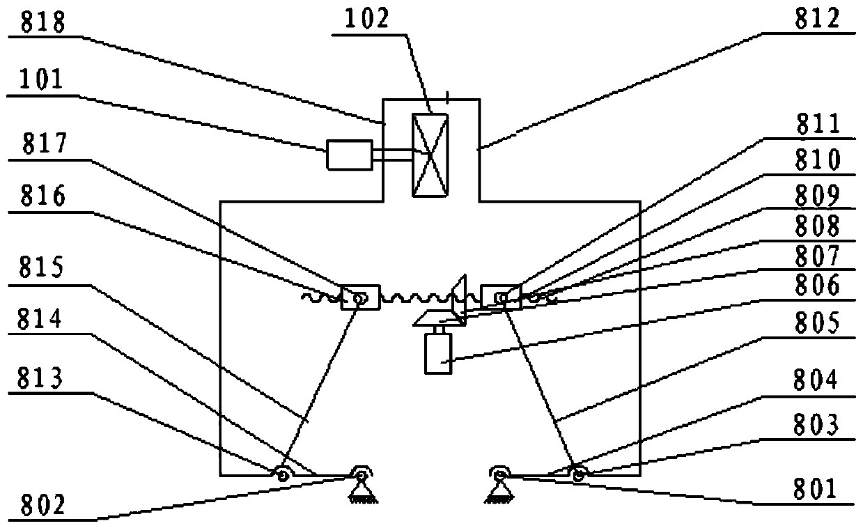
[0043] Such as image 3 As shown, the front opening and closing mechanism 8 includes a first bracket 812, a second bracket 818, a first linkage mechanism, a second linkage mechanism and a linear drive mechanism, wherein the linear drive mechanism is arranged on the front arm 3, The first link mechanism and the second link mechanism are respectively located on both sides of the linear drive mechanism, and are both connected to the front arm 3 and the output end of the linear drive mechanism. The first bracket 812 and One end of the second bracket 818 is respectively connected with the first linkage mechanism and the second linkage mechanism, and the other end of the first bracket 812 and the second bracket 818 is a closed end, and correspondingly, the front traveling mechanism 1 is set on the first bracket 812 or the second bracket 818 close to the closed end, the linear drive mechanism drives the first link mechanism and the second link mechanism on both sides to move, thereby...

Embodiment 2

[0053] Such as Figure 4 As shown, the front opening and closing mechanism 8 includes a first bracket 812, a second bracket 818, a first linkage mechanism, a second linkage mechanism and a linear drive mechanism, wherein the linear drive mechanism is arranged on the front arm 3, The first link mechanism and the second link mechanism are respectively located on both sides of the linear drive mechanism, and are both connected to the front arm 3 and the output end of the linear drive mechanism. The first bracket 812 and One end of the second bracket 818 is respectively connected with the first linkage mechanism and the second linkage mechanism, and the other end of the first bracket 812 and the second bracket 818 is a closed end, and correspondingly, the front traveling mechanism 1 is set on the first bracket 812 or the second bracket 818 close to the closed end, the linear drive mechanism drives the first link mechanism and the second link mechanism on both sides to move, thereb...


PUM


Abstract

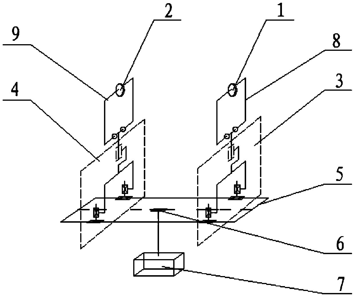
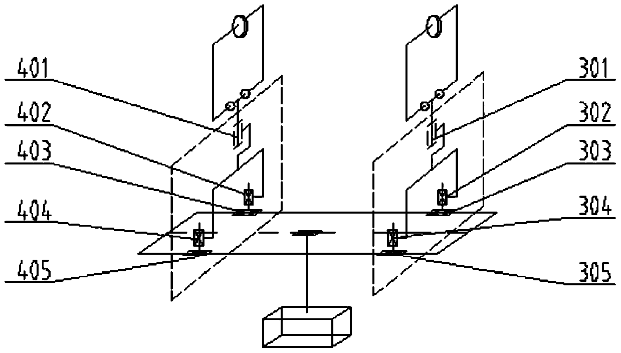
The invention relates to a mobile robot mechanism, and particularly relates to an inspection robot mechanism applicable to narrow inspection operation space. The inspection robot mechanism comprises a front walking mechanism, a rear walking mechanism, a front arm, a rear arm, a front opening and closing mechanism, a rear opening and closing mechanism, a guide rail and a box body, wherein the box body is arranged below the guide rail and is in sliding connection with the guide rail; the front arm and the rear arm are arranged above the guide rail and are in sliding connection with the guide rail; the front opening and closing mechanism and the rear opening and closing mechanism are respectively hinged at the tail ends of the front arm and the rear arm; the front walking mechanism and the rear walking mechanism are respectively arranged on the front opening and closing mechanism and the rear opening and closing mechanism; and the inspection robot mechanism walks on a transmission line through the front walking mechanism and the rear walking mechanism, and inspection operation is carried out. The inspection robot mechanism has the advantages of strong obstacle crossing ability, little operation space and good safety protection.

Description

technical field [0001] The invention relates to a mobile robot mechanism, in particular to an inspection robot mechanism suitable for narrow inspection work spaces. Background technique [0002] The transmission line is an extremely important part of the power system. In order to ensure its safe and stable operation, regular inspections are required. The methods currently used mainly include manual inspection, helicopter inspection and robot inspection. Among them, manual inspection is inefficient, labor-intensive, and dangerous; helicopter inspection is expensive, and the quality of inspection is easily affected by the climate. International research on transmission line inspection robot technology began in the 1980s. According to whether the robot mechanism has the function of crossing tower obstacles, inspection robots can be divided into first-class inspection robots and inspection robots with obstacle-surmounting functions. Inspection robot, the inspection robot in th...

Claims


Application Information

Patent Timeline
Patent Type & Authority Patents(China)
IPC IPC(8): H02G1/02
CPCH02G1/02
Inventor 王洪光凌烈王天龙景凤仁刘爱华孙鹏常勇
Owner SHENYANG INST OF AUTOMATION - CHINESE ACAD OF SCI
Learn More