
Carbon Fiber Multiaxial Vibration Spreading Device

A multi-axial, carbon fiber technology, applied in the direction of textiles and papermaking, to achieve the effect of increasing the unfolded area

Active Publication Date: 2019-02-26
聚合兴企业有限公司
View PDF8 Cites 0 Cited by
  • Summary
  • Abstract
  • Description
  • Claims
  • Application Information

AI Technical Summary

Problems solved by technology

[0002] Existing carbon fiber bundles are composed of a lot of fibers, as commonly used in the field as 3K, 6K, 12K, 24K, 48K, which means that a single carbon fiber bundle contains 3,000 to 48,000 fibers , in actual use, the carbon fiber bundle will be formed into a cloth shape by spreading technology, so that the carbon fiber cloth can be covered with multiple layers on the structure to be strengthened, that is, the carbon fiber can provide the application function of light weight and sufficient structural strength. When the carbon fiber bundle The larger the expanded surface area, the lighter (thinner) the weight per unit area of ​​the carbon fiber can be. Therefore, under the same coating thickness, the thinner the carbon fiber cloth can cover more layers, and the more layers When the carbon fiber cloth is cross-wrapped at different angles, the reinforcement quality will be better. Therefore, how to spread the carbon fiber bundles more evenly is the goal that this field has been working hard for. The main method of the device is to use multiple rollers to roll the carbon fiber bundles, and use the change of the roller tension to gradually expand the carbon fiber bundles under pressure. The expansion is more uniform, and the common improvement methods include controlling the diameter of the roller and changing the surface roughness of the roller. Although both can increase the expansion area, it is not difficult to find that there are still some shortcomings in the above existing structure. The main reason is that there is still room for improvement in the usual way of spreading yarns, which is the technical problem that the present invention intends to overcome

Method used


Image

  • Carbon Fiber Multiaxial Vibration Spreading Device
  • Carbon Fiber Multiaxial Vibration Spreading Device
  • Carbon Fiber Multiaxial Vibration Spreading Device

Examples


Embodiment Construction

[0044] The present invention will be further described below in conjunction with the accompanying drawings and specific embodiments, so that those skilled in the art can better understand the present invention and implement it, but the examples given are not intended to limit the present invention.

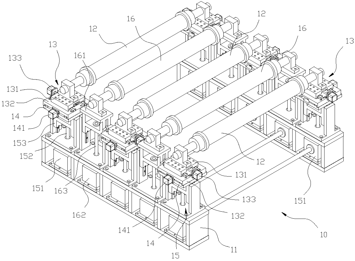
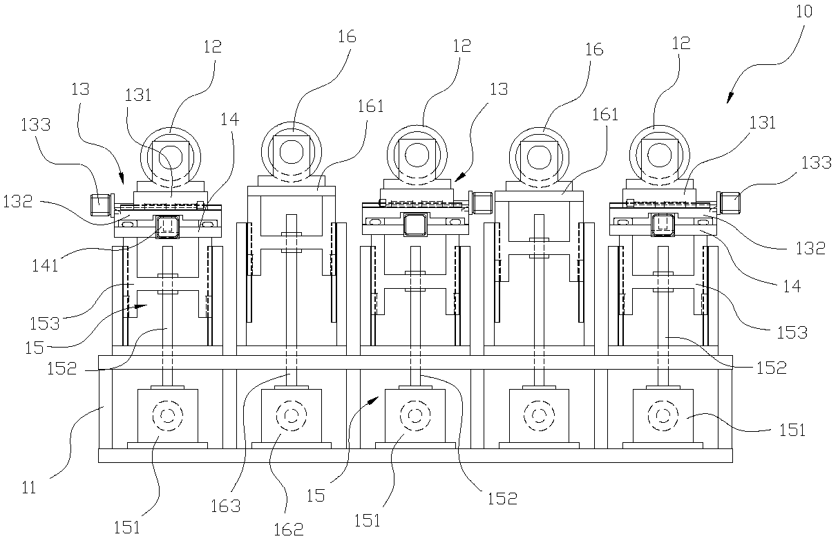
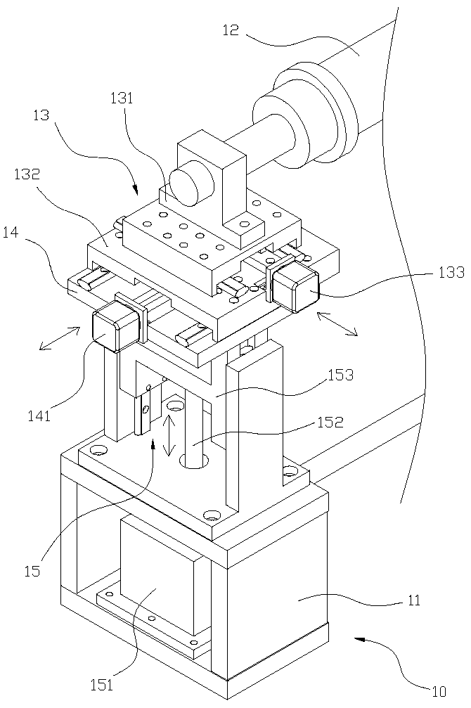
[0045] first please Figure 1 to Figure 3 As shown, the present invention provides a carbon fiber multi-axial vibration spreading device, wherein: a spreading device 10 is arranged in parallel with a plurality of spreading wheels 12 with a frame body 11, and the spreading device 10 uses a plurality of first An actuator 13 independently pivots the plurality of yarn spreading wheels 12, and the first actuator 13 drives the yarn spreading wheels 12 to perform one axial displacement of reciprocating back and forth, reciprocating left and right, or reciprocating up and down relative to the frame body 11. In the yarn spreading device 10, multiple second actuators 14 are independently co...


PUM


Abstract

The invention provides a yarn spreading device characterized by multi-axial vibration of carbon fibers. The yarn spreading device comprises a rack body; a plurality of yarn spreading wheels are arranged on the rack body in parallel; the yarn spreading device is characterized in that the multiple yarn spreading wheels are arranged on multiple first actuators in a pivoted manner independently; a plurality of second actuators are independently connected with the first actuators; a plurality of third actuators are independently connected with the second actuators; the third actuators are connected to the rack; the displacement directions of the first actuators, the second actuators and the third actuators do not coincide; each independent yarn spreading wheel of the yarn spreading device can be controlled to perform no displacement, single-axial displacement, bi-axial displacement or tri-axial displacement, and the frequency and amplitude of the displacement can be adjusted according to using requirements, so that the spreading area of carbon fiber bundles can be increased.

Description

technical field [0001] The invention relates to a rolling yarn spreading device, in particular to a carbon fiber multi-axial vibration spreading device which can improve the yarn spreading effect. Background technique [0002] Existing carbon fiber bundles are composed of a lot of fibers, as commonly used in the field as 3K, 6K, 12K, 24K, 48K, which means that a single carbon fiber bundle contains 3,000 to 48,000 fibers , in actual use, the carbon fiber bundle will be formed into a cloth shape by spreading technology, so that the carbon fiber cloth can be covered with multiple layers on the structure to be strengthened, that is, the carbon fiber can provide the application function of light weight and sufficient structural strength. When the carbon fiber bundle The larger the expanded surface area, the lighter (thinner) the weight per unit area of ​​the carbon fiber can be. Therefore, under the same coating thickness, the thinner the carbon fiber cloth can cover more layers,...

Claims


Application Information

Patent Timeline
Patent Type & Authority Patents(China)
IPC IPC(8): D02J1/18
CPCD02J1/18
Inventor 王胜福
Owner 聚合兴企业有限公司
Learn More