Clamping mechanism of glue binding machine

A technology of clamping mechanism and glue binding machine, which is applied to binding adhesives, book binding, printing, etc., which can solve problems such as deviation, complex structure, and affecting the neatness and beauty of books.

Inactive Publication Date: 2017-06-23
陈迪
View PDF1 Cites 0 Cited by
  • Summary
  • Abstract
  • Description
  • Claims
  • Application Information

AI Technical Summary

Problems solved by technology

The output shaft of the motor is connected to the two-way screw through chain transmission; two ends of the two-way screw are respectively fixed with a driving sprocket, and two unidirectional screw are respectively fixed with a driven sprocket, and the two driving sprockets are respectively connected to the corresponding The driven sprocket is connected by a chain; two guide plates are symmetrically arranged at both ends of the two-way screw rod, and guide holes are opened at both ends of each guide plate; the guide holes at one end of the two guide plates are threaded with the two-way screw rod The guide holes at the other end are respectively threaded with the corresponding one-way screw rods; the side walls of the two guide plates are fixed with splints, and the two splints are set opposite to each other; the linear bearing is fixed at one end of the clamping frame, clamping the machine The other end of the frame is fixed with two pin shafts; two pin shafts are sleeved with a roller. This structure can effectively reduce vibration, but the structure is complicated, and because the splints on both sides can move, it is easy to cause damage due to wear, etc. The center position of the two splints deviates from the center of the rear cover, which affects the neatness and beauty of the book after glue binding

Method used


Image

  • Clamping mechanism of glue binding machine
  • Clamping mechanism of glue binding machine

Examples


Embodiment Construction

[0014] The present invention will be further described in detail below in conjunction with the accompanying drawings and specific embodiments.

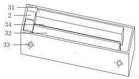
[0015] Such as figure 1 and figure 2 As shown, a clamping mechanism of a glue binding machine in the present invention includes a clamping frame 1, a motor 2 and a clamping device 3, and the clamping device 3 includes a fixed plate fixedly arranged on the clamping frame 1 in a parallel manner 31 and a moving plate 32 that can move relatively, the two sides of the two screw rods 33 are symmetrically connected to the bottom of the fixed plate 31 and the moving plate 32, and the driving wheel of the motor 2 and the screw rod 33 near the side of the motor 2 adopts a belt or a chain Correspondingly, a driven wheel is arranged between the two screw mandrels 33, and the two driven wheels are connected by a chain or a belt.

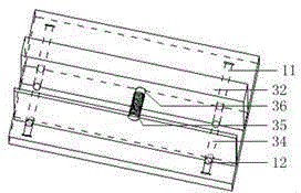
[0016] Such as figure 2 As shown, the opposite side of the moving plate 32 and the fixed plate 31 is provided wit...


PUM


Abstract

The invention discloses a clamping mechanism of a glue binding machine. The clamping mechanism comprises a book clamping frame (1), a motor (2), and a clamping and pressing device (3). The clamping and pressing device (3) comprises a fixed plate (31) and a movable plate (32), which are parallel to each other. The fixed plate (31) is fixedly arranged on the book clamping frame (1). The movable plate (32) is connected to the motor (2) through a screw rod (32). A clamping and pressing plate (34) is connected to the movable plate (32) through a pressure spring (35). Through the abovementioned structure, the fixed plate (31) is fixed and is capable of reducing the displacement deviation caused by wear of machine, thus the neatness and appearance of books are both improved after glue binding, the pressure spring is arranged between the clamping and pressing plate (34) and the movable plate (32) so as to reduce the vibration effectively, and the paper is easy to place therefore.

Description

technical field [0001] The invention relates to a glue binding machine assembly, in particular to a clamping mechanism of a glue binding machine. Background technique [0002] The glue binding machine is a machine that integrates loose paper or discrete books into books after being glued on the side. When in use, now stack the loose paper or discrete books and place them in the clamping mechanism of the glue binding machine, and treat them with a milling cutter. After milling grooves on the sides of glue-bound materials, apply hot melt adhesive to the sides after milling grooves through a glue pot, so as to integrate loose paper or discrete books into books. [0003] Chinese Patent No. CN203844440U discloses a kind of adhesive binding machine clip mechanism. The output shaft of the motor is connected to the two-way screw through chain transmission; two ends of the two-way screw are respectively fixed with a driving sprocket, and two unidirectional screw are respectively f...

Claims


Application Information

Patent Timeline
Patent Type & Authority Applications(China)
IPC IPC(8): B42C9/00
CPCB42C9/0006
Inventor 陈迪
Owner 陈迪
Why Eureka
Try Eureka