
Q-frame t-aperture compound emission imaging method and system applied to ultrasonic probe

An ultrasound probe and imaging method technology, applied in the ultrasound field, can solve the problems of complex probe design, increase the number of array elements and probe cables, reduce image contrast, etc., and achieve the effects of improving ultrasound image quality and reducing partial volume effect.

Active Publication Date: 2020-04-14
VINNO TECH (SUZHOU) CO LTD
View PDF5 Cites 0 Cited by
  • Summary
  • Abstract
  • Description
  • Claims
  • Application Information

AI Technical Summary

Problems solved by technology

[0005] The two-dimensional probe imaging transmitter can realize electronic focusing, and the receiving end can realize electronic dynamic focusing, so the lateral and lateral beam width can be well controlled, but the two-dimensional probe will greatly increase the number of array elements and the number of probe cables. The design is quite complicated, and it also puts forward higher requirements for the design of the system, and it has not been widely used yet
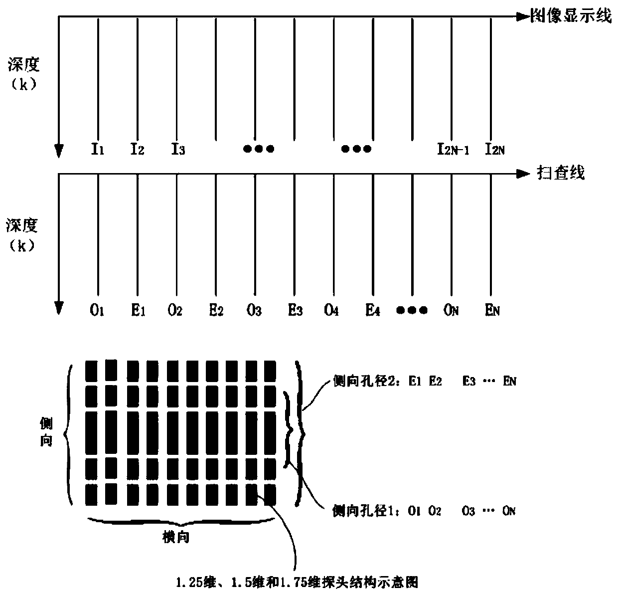
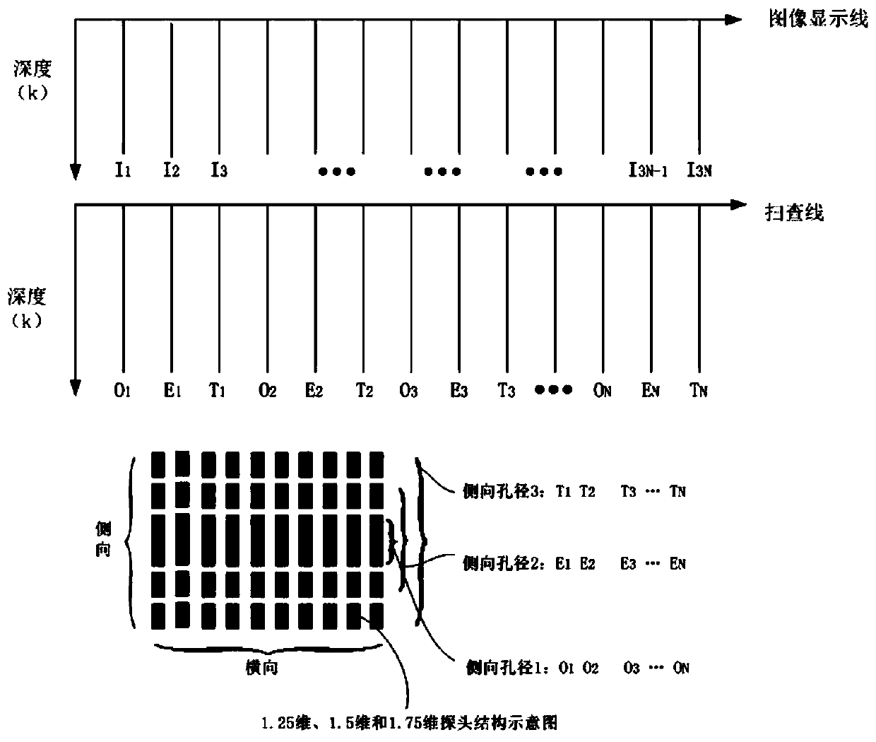
[0007] However, for the transmitting ends of the 1.25-dimensional, 1.5-dimensional and 1.75-dimensional probes, the 1.25-dimensional, 1.5-dimensional and 1.75-dimensional probes all use acoustic lenses to achieve mechanical focusing with a fixed focus, and at the same time, they can be adjusted relative to their lateral emission apertures; In this way, the 1.25-dimensional, 1.5-dimensional and 1.75-dimensional probes generally have a smaller lateral aperture when the emission focus is in the near-field area to achieve a narrow lateral beam width, reduce partial volume effects, and improve image contrast. However, a small lateral aperture will lead to a wide beam in the far field, and the energy is low, and its penetration and image contrast will decrease; on the contrary, when the transmitting focus is in the far field area, the lateral aperture should be opened larger to achieve Narrow side beams in the far-field area reduce partial volume effects and improve image contrast, but large lateral apertures will increase the volume effect in the near-field area and reduce image contrast
Correspondingly, the transmitting end of the 1.25-dimensional, 1.5-dimensional and 1.75-dimensional probes still faces the problem of narrow lateral beam near the mechanical focus, wide lateral beam far away from the mechanical focal point, and uneven beam width
[0008] For the transmitting end of the 1.25-dimensional, 1.5-dimensional and 1.75-dimensional probes, some solutions have been proposed at present, and a multi-focus acoustic lens is proposed to realize the multi-focus control of the transmitting end and improve the consistency of the lateral beam of the transmitting end; however, this The multi-focal acoustic lens design needs to design acoustic lenses with different curvatures in the lateral direction along the center of the lateral aperture to both sides. The design is more complicated, and it is generally used less

Method used


Image

  • Q-frame t-aperture compound emission imaging method and system applied to ultrasonic probe
  • Q-frame t-aperture compound emission imaging method and system applied to ultrasonic probe
  • Q-frame t-aperture compound emission imaging method and system applied to ultrasonic probe

Examples


Embodiment Construction

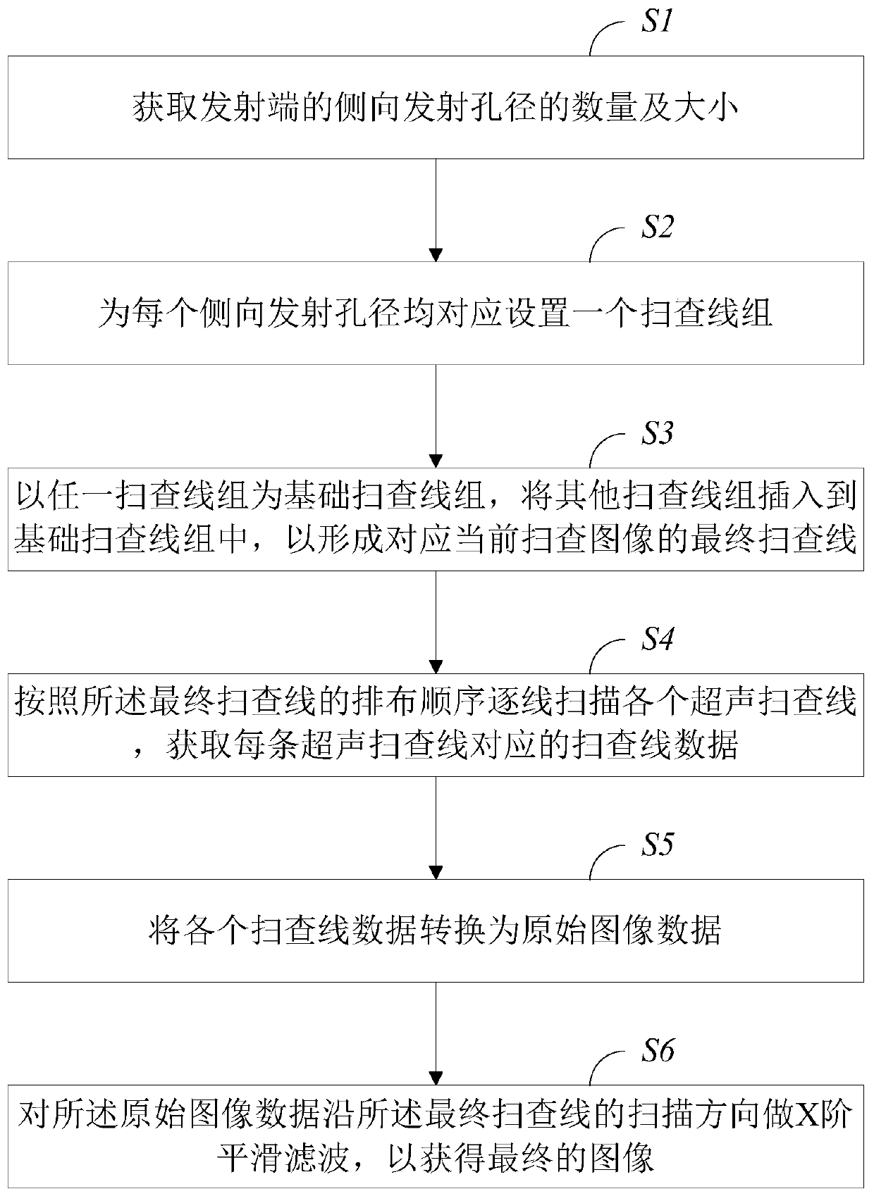
[0080] The present invention will be described in detail below in conjunction with specific embodiments shown in the accompanying drawings. However, these embodiments do not limit the present invention, and any structural, method, or functional changes made by those skilled in the art according to these embodiments are included in the protection scope of the present invention.

[0081] It should be noted that in the specific application examples of the present invention, it mainly solves the transmitting end of the 1.25-dimensional, 1.5-dimensional and 1.75-dimensional probes mentioned in the background technology, and realizes the mechanical focusing of the fixed focus through the acoustic lens, resulting in near-field area The volume effect increases which reduces the contrast of the image.

[0082] Such as figure 1 As shown, in the first embodiment of the present invention, a Q-frame T-aperture composite emission imaging method applied to an ultrasonic probe is provided. I...


PUM


Abstract

The invention provides a Q-frame T-aperture compound emission imaging method and system applied to an ultrasonic probe. The method comprises: setting a scan line set corresponding to each lateral emission aperture, and with any scan line set as a basic scan line, inserting other scan line set in the basic scan line to form final scan lines corresponding to a current scan image; scanning various ultrasonic scan lines one by one to obtain scan line data corresponding to each ultrasonic scan line; in the scanning process, for each ultrasonic scan line, using a lateral emission aperture corresponding to the scan line set where the ultrasonic scan line belongs for scan; converting each scan line data into original image data; and performing X-order smoothing filtering on the original image data in a scanning direction of the final scan lines to obtain a final image. According to the invention, the problem of uneven width of acoustic beams from 1.25-dimensional, 1.5-dimensional and 1.75-dimensional probe transmitting terminals to near, middle and far fields of acoustic beams is solved under the premise of losing no frame frequency, and the ultrasonic image quality is improved.

Description

technical field [0001] The invention relates to the field of ultrasound, in particular to a Q-frame T-aperture compound emission imaging method and system applied to an ultrasound probe. Background technique [0002] With its real-time imaging, fast imaging speed, non-invasive and radiation-free, continuous dynamic and repeatable scanning features, medical ultrasound imaging has been more and more widely used in clinical practice, and has become an indispensable and important imaging method in the field of medical imaging. one. [0003] The most widely used one-dimensional probes in clinical practice include linear array, arc array and phased array; their lateral and longitudinal resolutions are excellent, but their lateral resolution is greatly limited. Since the size of the lateral aperture of the one-dimensional probe is fixed, the lateral focusing is generally achieved through the acoustic lens to achieve the mechanical focusing of the fixed focus, so the lateral acoust...

Claims


Application Information

Patent Timeline
Patent Type & Authority Patents(China)
IPC IPC(8): A61B8/00
CPCA61B8/48A61B8/5207
Inventor 吴方刚郭建军
Owner VINNO TECH (SUZHOU) CO LTD
Learn More