Bilinear interpolation method-based laser galvanometer graphic correction algorithm

A technology of bilinear interpolation and laser galvanometer, applied in computing, image enhancement, image data processing, etc., can solve problems such as the influence of scanning accuracy of galvanometer laser scanning system

Inactive Publication Date: 2017-06-09
深圳市神臂智能科技有限公司
View PDF4 Cites 5 Cited by
  • Summary
  • Abstract
  • Description
  • Claims
  • Application Information

AI Technical Summary

Problems solved by technology

[0011] In addition, the scanning accuracy of the galvanometer laser scanning system is also affected by the mechanical installation error and the control system

Method used


Image

  • Bilinear interpolation method-based laser galvanometer graphic correction algorithm
  • Bilinear interpolation method-based laser galvanometer graphic correction algorithm
  • Bilinear interpolation method-based laser galvanometer graphic correction algorithm

Examples


Embodiment Construction

[0085] Through the following specific examples and appended Figures 1 to 9 The present invention is described in detail, but not as a limitation of the present invention.

[0086] Provide a laser galvanometer image correction algorithm based on bilinear interpolation method, the correction logic flow is shown in the figure Figure 7 .

[0087] The specific steps are as follows:

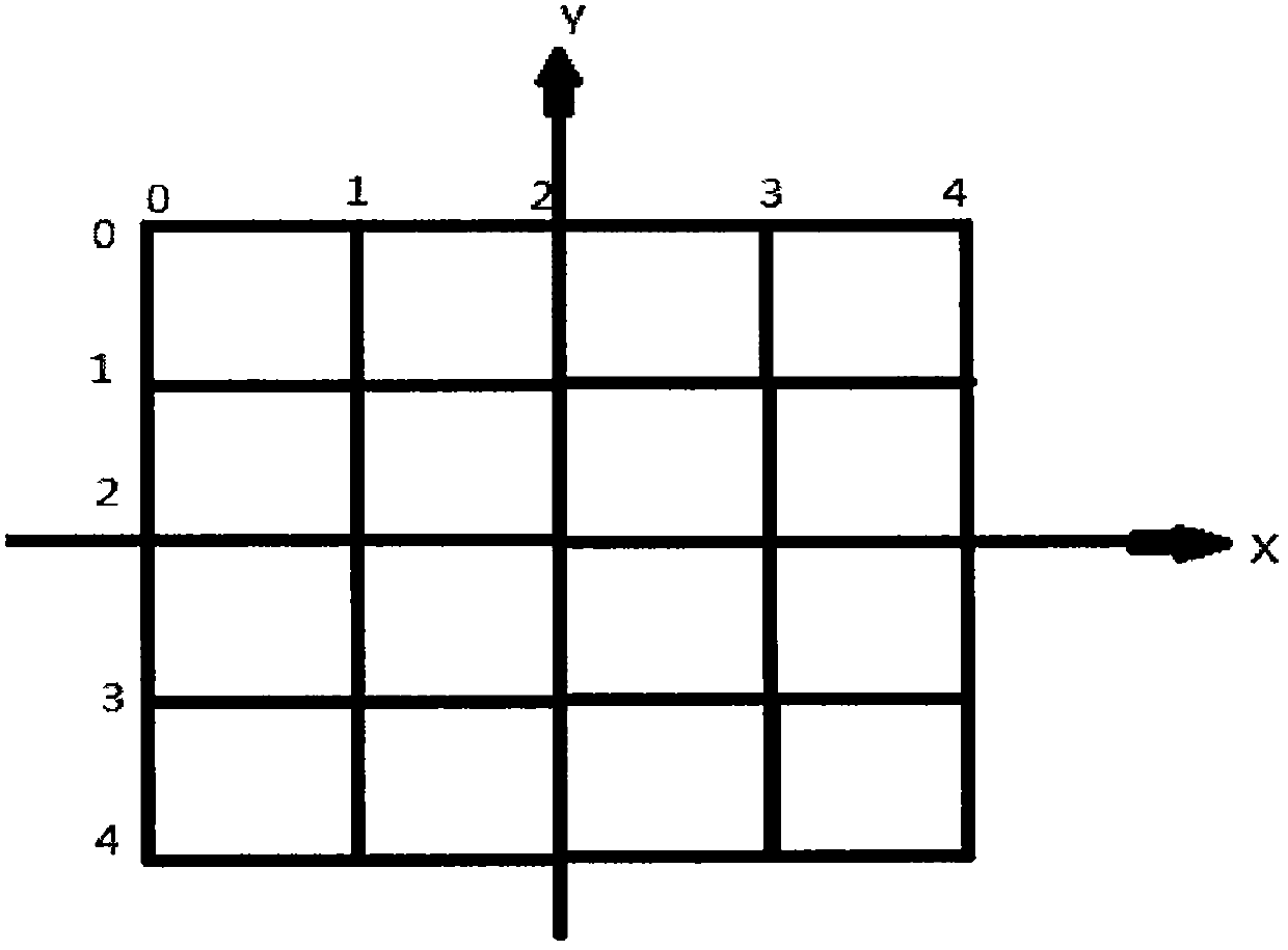
[0088] 1. Divide a square with a side length of m into (2n+1) rows (2n+1) columns, that is, from row 0 to row 2n, from column 0 to column 2n; then row n The point of intersection with the nth column is the origin of the coordinates, and a coordinate system is established; (as attached figure 1 shown)

[0089] 2. In the case of uncorrected laser marking; then according to the principle from left to right and from top to bottom, measure the coordinates of each point after marking, and establish the x-axis coordinates corresponding to the measured intersection points , the array of y-axis coordinates...


PUM


Abstract

The present invention relates to a bilinear interpolation method-based laser galvanometer graphic correction algorithm and the core of the algorithm is composed of a bilinear interpolation method. Mathematically, the bilinear interpolation method is the extension of the linear interpolation for an interpolation function containing two variables. The core idea of the laser galvanometer graphic correction algorithm is composed of the primary linear interpolation conducted respectively in two directions. Experiments show that, the correction algorithm can eliminate the linear distortion and the nonlinear distortion occurred during the graphic scanning process of a laser galvanometer. Meanwhile, the algorithm can correct the comprehensive error generated during the scanning process of the laser galvanometer. Therefore, the algorithm provides a satisfactory correction effect for the correction of laser marking graphics.

Description

technical field [0001] The invention relates to the field of laser vibrating mirror pattern correction algorithms, in particular to a laser vibrating mirror pattern correction algorithm based on a bilinear interpolation method. Background technique [0002] The galvanometer scanning marking head is mainly composed of XY scanning mirror (mirror), field mirror, galvanometer and computer-controlled marking software. Its working principle is: the laser beam is incident on two XY scanning mirrors ( Mirror), the computer controls the reflection angle of the XY scanning mirror (mirror), so that the light beam can be scanned along the X and Y axes after passing through the two XY scanning mirrors (mirror), even if the laser beam is deflected, the Even with a certain power density, the focus of the laser falls on the marking material, and the focus can be moved as required, so that the laser beam can be used to leave a permanent mark on the surface of the target material. The focuse...

Claims


Application Information

Patent Timeline
Patent Type & Authority Applications(China)
IPC IPC(8): G06T5/00
CPCG06T5/80
Inventor 龙兵
Owner 深圳市神臂智能科技有限公司
Why Eureka
Try Eureka