
Topological structure for voltage source converter unit and control method

A voltage source converter and topology technology, which is applied in electrical components, power transmission AC networks, circuit devices, etc., can solve problems such as short circuit of voltage source converters and failure of inverter switching

Active Publication Date: 2017-05-31
NR ELECTRIC CO LTD +1
View PDF6 Cites 18 Cited by
  • Summary
  • Abstract
  • Description
  • Claims
  • Application Information

AI Technical Summary

Problems solved by technology

[0005] For the series hybrid HVDC transmission system and the series HVDC flexible transmission system, if the topological structure of the thyristor converter series HVDC transmission system is still used for the online switching of the voltage source converter, due to the existence of capacitance storage in the voltage source converter It will cause the voltage source converter to have a serious fault similar to the short circuit of the positive and negative poles on the DC side, resulting in the failure of the converter to switch on and off. At present, it has not been seen that the voltage source converter in the series DC transmission system can be switched on and off online. Therefore, it is necessary to combine the characteristics of voltage source converters to provide a topology and control method that can realize online switching of voltage source converters, so as to meet the requirements of series hybrid DC transmission system or series Operation and maintenance needs of HVDC flexible HVDC system

Method used


Image

  • Topological structure for voltage source converter unit and control method
  • Topological structure for voltage source converter unit and control method
  • Topological structure for voltage source converter unit and control method

Examples


Embodiment Construction

[0074] The technical solutions of the present invention will be described in detail below in conjunction with the accompanying drawings and specific embodiments.

[0075] The present invention provides a voltage source converter unit topology and control method, which are used to realize the online input and online withdrawal of a single voltage source converter when two or more DC pole converters of a direct current transmission system operate in series. It can meet the operation and maintenance needs of series hybrid direct current transmission system or series flexible direct current transmission system.

[0076] In order to achieve the above object, the solution of the present invention is:

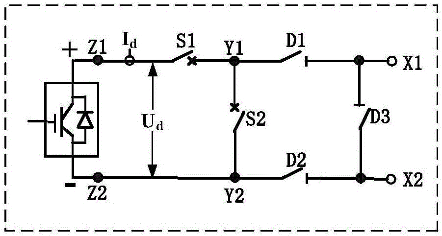
[0077] The present invention provides a voltage source converter unit topology for realizing the online input and online withdrawal of the voltage source converter, and the voltage source converter unit includes: first unit isolation switches (D1) connected in series , unit isolating...


PUM


Abstract

The invention discloses a topological structure for a voltage source converter unit. The topological structure comprises a first unit isolated knife switch (D1), a unit isolated switch (S1), a voltage source converter, a second unit isolated knife switch (D2) and a connecting lead which are serially connected, a unit bypass knife switch (D3) and a unit bypass switch (S2), wherein the beginning end and the tail end of the series loop are used as a first direct-current endpoint (X1) and a second direct-current endpoint (X2) of the voltage source converter unit respectively; the unit bypass knife switch (D3) is connected between the first direct-current endpoint (X1) and the second direct-current endpoint (X2) in a crossed manner; and the unit bypass switch (S2) is connected between the end near the voltage source converter (Y1) of the first unit isolated knife switch (D1) and the end near the voltage source converter (Y2) of the second unit isolated knife switch (D2) in the crossed manner. The invention also discloses a control method corresponding to the topological structure. The topological structure and the control method realize online investment and quit of the single voltage source converter when two or more than two converters are in series operation in a direct-current transmission system.

Description

technical field [0001] The invention belongs to the technical field of direct current transmission, and in particular relates to a voltage source converter unit topology structure and a control method. Background technique [0002] HVDC systems can be divided into two types: conventional HVDC systems based on thyristor converters (LCC-HVDC) and flexible HVDC systems based on fully controlled voltage source converters (VSC-HVDC). Conventional DC transmission systems are low in cost, low in loss, and mature in operation technology. Most of the DC transmission systems currently in operation in the world are LCC-HVDC systems. The system is highly dependent, needs to absorb a large amount of reactive power, and the converter station occupies a large area; while the new generation of flexible DC transmission system has the ability to realize decoupling control of active power and reactive power, and can contribute to the passive network. It has the advantages of power supply, com...

Claims


Application Information

Patent Timeline
IPC IPC(8): H02J3/36H02J3/00
CPCH02J3/36H02J3/0073Y02E60/60
Inventor 鲁江卢宇董云龙汪楠楠王永平赵文强田杰李海英
Owner NR ELECTRIC CO LTD
Learn More