
Synchronous control method and synchronous control device for double driving motors at double sides

A dual-side drive, synchronous control technology, applied in adaptive control, general control system, control/regulation system, etc., can solve problems such as low synchronization accuracy and low shutdown accuracy

Active Publication Date: 2017-05-31
北京二十一世纪科技发展有限公司
View PDF7 Cites 5 Cited by
  • Summary
  • Abstract
  • Description
  • Claims
  • Application Information

AI Technical Summary

Problems solved by technology

[0006] In the existing speed control plus photoelectric switch positioning control method on the main motor side, after receiving the photoelectric signal of the photoelectric switch, it will stop after speed control (after reducing the speed). The position of the stop is greatly affected by the process accuracy of speed control. Low precision; the slave motor side is synchronized solely based on the ground current information implemented by the host. When the load on the master motor side is different from the load on the slave motor side, the synchronization accuracy of the master motor side and the slave motor side of the controlled object will be low.

Method used


Image

  • Synchronous control method and synchronous control device for double driving motors at double sides
  • Synchronous control method and synchronous control device for double driving motors at double sides
  • Synchronous control method and synchronous control device for double driving motors at double sides

Examples


Embodiment 1

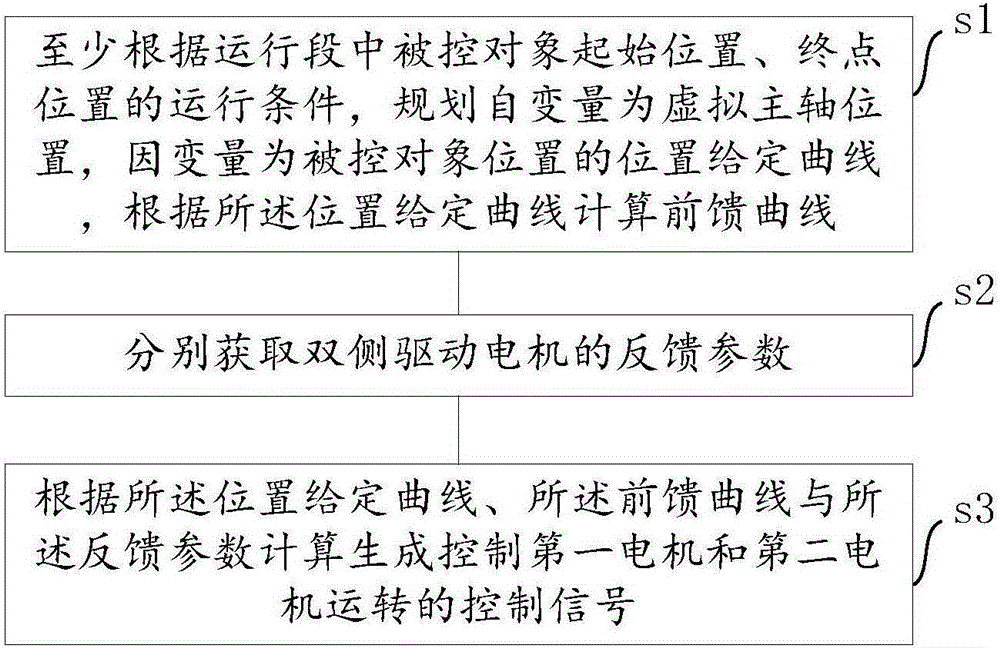
[0063] Such as figure 2 As shown, a synchronous control method of a double-sided drive motor proposed by an embodiment of the present invention can be applied to a synchronous control device of a double-sided drive motor, especially a quasi-rigid synchronous control device (that is, a quasi-rigid The synchronous control device refers to the transmission mechanism connecting the double-sided motor and the controlled object as a flexible transmission mechanism); the double-sided drive motor in the double-sided drive motor synchronous control device drives the same controlled object, and the controlled object is controlled. During the driving process, the position of the controlled object moves from the initial position to the end position;

[0064] The method for synchronous control of the double-sided driving motor comprises the steps of:

[0065] Step s1, at least according to the operating conditions of the starting position and the end position of the controlled object in ...

Embodiment 2

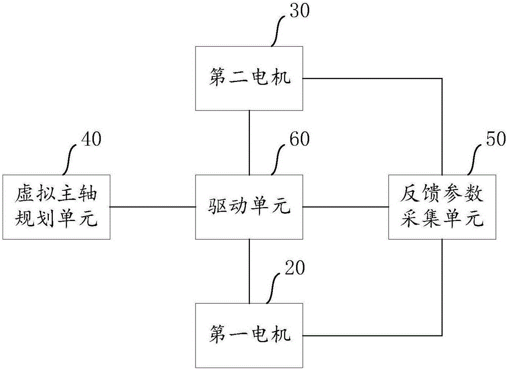
[0113] Such as image 3 , Figure 4 and Figure 5 As shown, a synchronous control device for a double-sided drive motor proposed in an embodiment of the present invention can be controlled by the synchronous control method for a double-sided drive motor described in the first embodiment above, and the synchronous control method described in the second embodiment The synchronous control method of the double-sided driving motors can directly adopt the synchronous control method of the double-sided driving motors provided in the first embodiment. The specific implementation method can refer to the relevant content described in the first embodiment above, and will not be repeated here. .

[0114] The synchronous control device for the drive motors on both sides consists of:

[0115] Accused 10;

[0116] The first motor 20 drives the first end of the controlled object 10 through the first transmission mechanism 21;

[0117] The second motor 30 drives the second end of the cont...


PUM


Abstract

The invention relates to a synchronous control method and a synchronous control device for double driving motors at double sides, wherein the method and the device relate to the field of control technology for double driving motors at the double sides. The method and the device mainly aim to improve synchronous control precision of the double driving motors at the double sides to a controlled object. The method comprises the steps of at least according to operation conditions of a controlled object starting position and a controlled object ending position in an operation period, planning a position-preset curve in which an independent variable is at a virtual main axis position and a dependent variable is at a controlled object position, and calculating a feedforward curve according to the position-preset curve, wherein the feedforward curve comprises a speed feedforward curve which corresponds with the position-preset curve, and a torque feedforward curve that corresponds with the position-preset curve; respectively acquiring feedback parameters of the double driving motors at the double sides; and generating a control signal for controlling operation of the first motor and the second motor according to the position-preset curve, the feedforward curve and the feedback parameters. Compared with prior art, the synchronous control method and the synchronous control device have advantages of high control precision and effective improvement of synchronous control precision of the double driving motors at the double sides to the controlled object.

Description

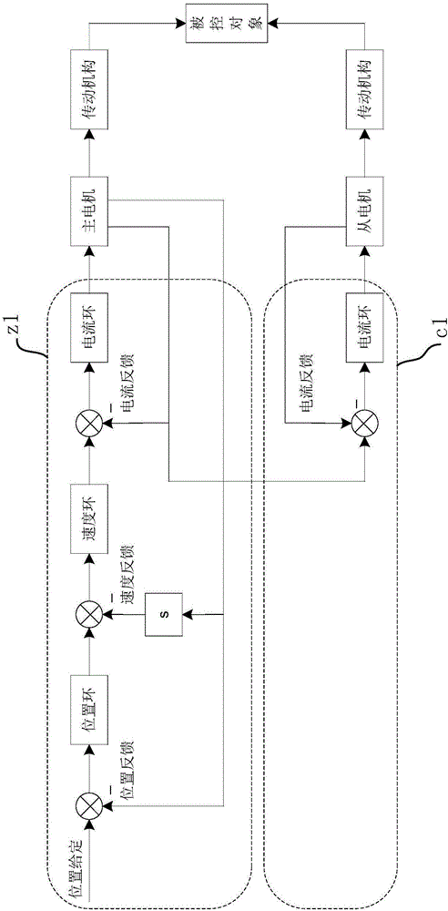
technical field [0001] The invention relates to the technical field of double-side drive motor control, in particular to a double-side drive quasi-rigid connection position synchronization control technology. Background technique [0002] For some mechanical equipment, it is necessary to configure double-sided driving motors to drive the same controlled object through a quasi-rigid (that is, flexible connection, such as a chain plus universal coupling) connection transmission mechanism. The transmission mechanism on the side drives the controlled object, and the slave motor side drives the controlled object through the transmission mechanism on the driving side. [0003] Such as figure 1 As shown, on the main motor side, photoelectric switch positioning or position semi-closed-loop control is often used on the main motor side to realize positioning. The main motor feeds back the position information, speed information, and current information to the main controller z1 in re...

Claims


Application Information

Patent Timeline
Patent Type & Authority Applications(China)
IPC IPC(8): G05B13/04
CPCG05B13/042
Inventor 李涛叶胜钱郝俊强刘铁龙
Owner 北京二十一世纪科技发展有限公司
Learn More