Telescopic arm barrel and crane boom

A telescopic boom and boom technology, which is applied in the field of lifting equipment, can solve the problems of complicated boom disassembly process and low maintenance efficiency, and achieve the effects of shortening the time required for disassembly, reducing disassembly steps and improving efficiency.

Active Publication Date: 2017-05-31
SANY PALFINGER SPECIAL VEHICLE
View PDF6 Cites 3 Cited by
  • Summary
  • Abstract
  • Description
  • Claims
  • Application Information

AI Technical Summary

Problems solved by technology

[0006] The purpose of the present invention is to provide a telescopic arm tube to solve the technical problems of the prior art that the disassembly process of the boom is relatively complicated and the maintenance efficiency is low

Method used


Image

  • Telescopic arm barrel and crane boom
  • Telescopic arm barrel and crane boom
  • Telescopic arm barrel and crane boom

Examples


Embodiment 1

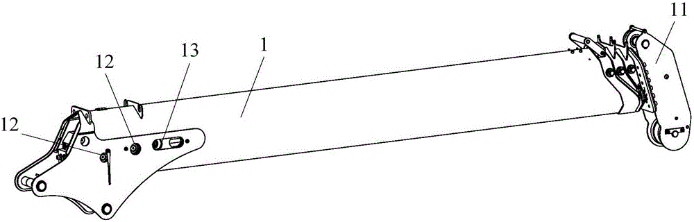
[0043] Such as figure 1 As shown, the telescopic arm tube 1 provided by the embodiment of the present invention includes: a plurality of joint arms that are telescopically sleeved sequentially from the outside to the inside, wherein one or more joint arms are provided with telescopic device installation for installing the telescopic device. Hole, on each section arm sleeved on the outer side of the section arm provided with the installation hole of the expansion device, there is correspondingly provided with the through hole 12 of the expansion device. The through holes 12 are aligned with each other.

[0044] When the telescopic boom tube 1 of the embodiment of the present invention is applied to the boom, the installation process of the boom is as follows: connect each section arm in turn, so that each section arm is sequentially fitted; then place the telescopic device in the innermost section arm , and connect the telescoping device with the joints to be connected when ea...

Embodiment 2

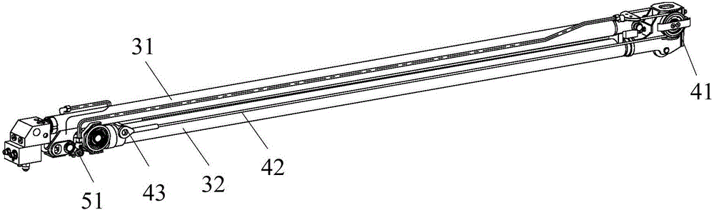
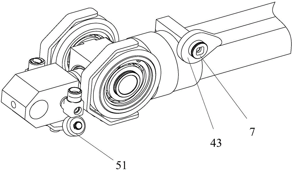
[0050] Such as Figure 1-11 As shown, the second embodiment of the present invention provides a lifting arm, which includes the telescopic boom tube 1 provided in the first embodiment above, and a telescopic device is installed in the telescopic boom tube 1 . Specifically, the telescopic device can be sent to the inside of the telescopic arm tube 1 from the arm tail of the telescopic arm tube 1 or the arm head 11. When the telescopic device is sent into the telescopic arm tube 1 from the arm tail of the telescopic arm tube 1, The structure of the telescopic arm barrel 1 does not need to be changed; when the telescopic device is sent into the interior of the telescopic arm barrel 1 from the arm head 11 of the telescopic arm barrel 1, the arm head 11 of the telescopic arm barrel 1 needs to be designed as a detachable structure, namely The cylinder body of the telescopic arm cylinder 1 is directly and detachably connected to the arm head 11 , for example, the cylinder body of the...


PUM


Abstract

The invention provides a telescopic arm barrel and a crane boom and relates to the technical field of crane equipment. The invention aims to solve the problem that the detaching process of the crane boom is relatively complicated, and the maintenance efficiency is relatively low. The telescopic arm barrel comprises a plurality of knuckle arms which successively sleeve from outside to inside in a telescopic manner, wherein a telescopic device mounting hole for mounting a telescopic device is formed in one or more knuckle arms, a telescopic device through hole is correspondingly formed in each knuckle arm which sleeves the outer side of the knuckle arm provided with the telescopic device mounting hole, and when each knuckle arm is in a full shrinking state, the corresponding telescopic device mounting hole and the telescopic device through hole are aligned to each other. The telescopic arm barrel is applied to the crane boom so as to improve the maintenance efficiency of the crane boom.

Description

technical field [0001] The invention relates to the technical field of hoisting equipment, in particular to a telescopic arm barrel and a lifting arm. Background technique [0002] The truck-mounted crane, also known as the truck-mounted crane, is a kind of equipment that realizes the lifting, turning, and hoisting of goods through the telescopic system of the hydraulic lift. It is usually assembled on a truck. The boom is the core component of the truck-mounted crane and an important load-bearing structural part in the lifting operation. [0003] At present, the boom is usually composed of a telescopic boom tube and a telescopic device. The telescopic boom tube includes a plurality of suitably articulated arms, and the telescopic device is connected with each articulated arm for driving each articulated arm to expand and contract. The telescoping device usually includes an oil cylinder. When the number of jibs is large, the boom also includes a rope row structure, which in...

Claims


Application Information

Patent Timeline
Patent Type & Authority Applications(China)
IPC IPC(8): B66C23/693B66C23/62
CPCB66C23/62B66C23/705
Inventor 陆进添周献华刘丹
Owner SANY PALFINGER SPECIAL VEHICLE
Why Eureka
Try Eureka