Electric drives and electric equipment

A technology for electric drive and electric equipment, which is used in motor control, AC motor control, estimation/correction of motor parameters, etc. Guarantee, poor current sharing effect, etc., to avoid the waste of human and financial resources, break monopoly and blockade, and reduce costs

Active Publication Date: 2019-11-01
UNIV OF SHANGHAI FOR SCI & TECH
View PDF2 Cites 0 Cited by
  • Summary
  • Abstract
  • Description
  • Claims
  • Application Information

AI Technical Summary

Problems solved by technology

Although the time of the turn-on process and the turn-off process is very short, the power switch tube cannot withstand the motor line current exceeding the maximum continuous operating current in this short period of time.
[0010] With the increase in the number of power switch tubes connected in parallel, it is more difficult to ensure the consistency of their switching characteristics, resulting in poorer current sharing effect, higher possibility of damage, and more serious problems
Since the parallel current sharing technology cannot ensure that any number of parallel power switch tubes are turned on and off at the same time, it seriously affects and limits the increase in the capacity of the high-current power converter, making the drive of a high-current motor a difficult task. hurdles to cross

Method used


Image

  • Electric drives and electric equipment
  • Electric drives and electric equipment
  • Electric drives and electric equipment

Examples


Embodiment Construction

[0029]The specific implementation manners of the present invention will be described below in conjunction with the accompanying drawings.

[0030] The electric driving device 10 is installed in electric equipment such as electric tools, quadcopters, electric vehicles, electric boats, industrial electric forklifts, and electric military equipment, and is used to drive the electric equipment.

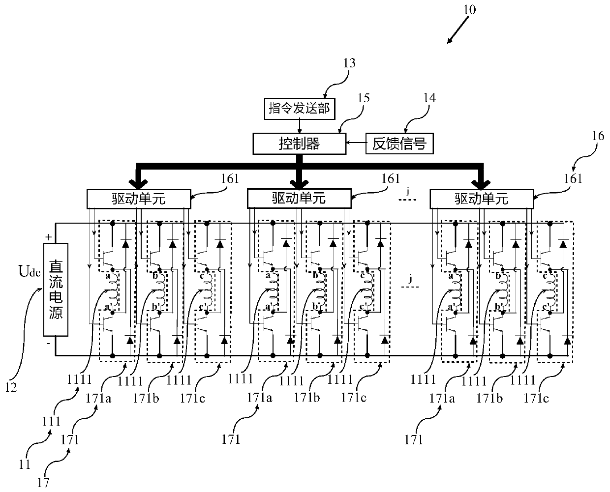
[0031] figure 1 is a schematic diagram of the circuit structure of the electric drive device in this embodiment.

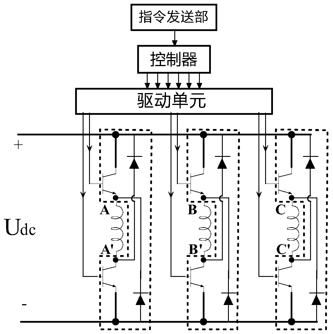
[0032] like figure 1 As shown, the electric driving device 10 includes a switched reluctance motor 11 , a DC power supply 12 , a command sending unit 13 , a feedback signal 14 , a controller 15 , a driver 16 and a power converter 17 .

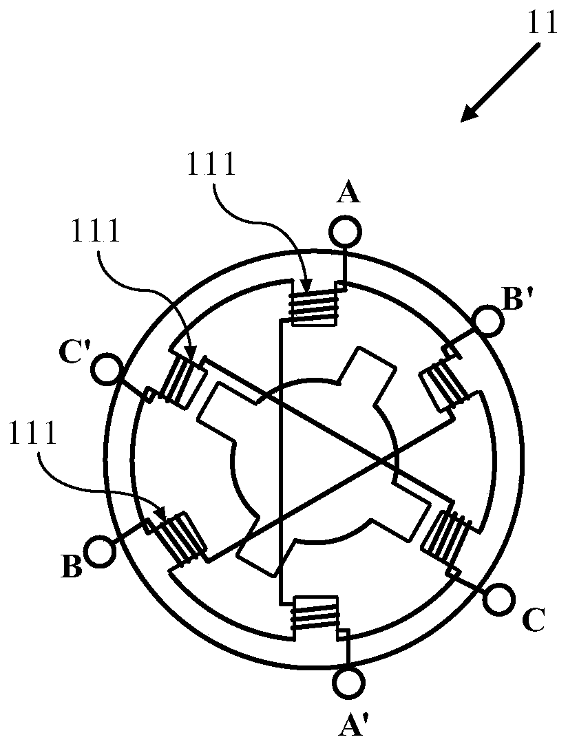
[0033] The switched reluctance motor 11 has a set of motor windings, the number of phases of the motor windings is k, a rated line voltage and a rated line current. The motor winding has j mutually independent polyphase winding units 111 ...


PUM


Abstract

The invention provides an electric driving device and electric equipment. The electric driving device provided by the invention is arranged in the electric equipment and used for driving the electric equipment and comprises a switch reluctance machine, a direct-current power supply, an instruction issue part, a feedback signal, a controller, a driver and a power converter. The electric driving device is characterized in that the switch reluctance machine comprises j multiphase winding units which are mutually independent and the same in parameters, the power converter comprises j power conversion units which are mutually independent and the same in parameters, the j power conversion units are correspondingly connected with the j multiphase winding units in a one-to-one mode, each power conversion unit comprises k power conversion circuits which are mutually in parallel connection and the same in parameters and used for providing k paths of currents for the corresponding multiphase winding units, the driver comprises j driving units which are mutually independent and the same in parameters, the j driving units are connected with the j power conversion units, the k is a positive integer larger than 2, and the j is a positive integer larger than 1.

Description

technical field [0001] The invention belongs to the field of switched reluctance motors, in particular to an electric driving device and electric equipment including the electric driving device. Background technique [0002] With the increase in the number of days and duration of smog in major cities, the country has become more and more strict on the exhaust emission management of fuel equipment; in addition, in a closed indoor working environment, the use of fuel equipment is prohibited; in addition, oil as an energy source It is non-renewable and will face depletion in a few decades. Therefore, electric equipment using electricity as an energy source, such as electric vehicles, electric forklifts and other electric equipment, is more and more favored by manufacturers and consumers. Not only does it have low pollution, it can provide electric energy through renewable energy, and compared with fuel equipment, it also has the advantages of high energy utilization rate, simp...

Claims


Application Information

Patent Timeline
Patent Type & Authority Patents(China)
IPC IPC(8): H02P25/092H02P25/16H02P23/14H02P6/28H02P29/028
CPCH02P23/14H02P25/16H02P29/027
Inventor 金爱娟李少龙
Owner UNIV OF SHANGHAI FOR SCI & TECH
Why Eureka
Try Eureka