
Cool-heat-electricity cogeneration microgrid system modeling method

A technology for combined cooling, heating and power supply and system modeling. It is applied in the fields of electrical digital data processing, instruments, and data processing applications. It can solve problems such as many mathematical models, lack of structural forms, and complex energy system analysis, and achieve easy expansion. Sexual, easy to understand, simple and clear structure

Inactive Publication Date: 2017-05-24
HUBEI UNIV OF TECH
View PDF5 Cites 4 Cited by
  • Summary
  • Abstract
  • Description
  • Claims
  • Application Information

AI Technical Summary

Problems solved by technology

Traditional modeling methods usually list several situations that may occur in the supply and demand relationship of the energy system in the form of enumeration, and establish a type of mathematical model for each situation. There are many types of mathematical models and lack of standard unified structural forms. Complicates the analysis of such energy systems

Method used


Image

  • Cool-heat-electricity cogeneration microgrid system modeling method
  • Cool-heat-electricity cogeneration microgrid system modeling method

Examples


Embodiment Construction

[0028] The above-mentioned content of the present invention will be described in further detail below through the embodiment form, but this should not be interpreted as the scope of the above-mentioned theme of the present invention is limited to the following embodiments, all technologies realized based on the above-mentioned content of the present invention belong to this invention the scope of the invention.

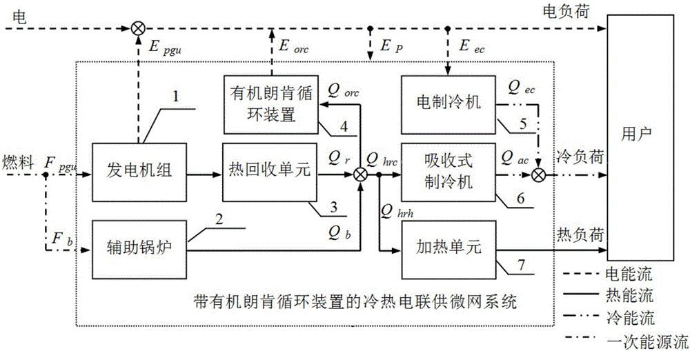
[0029] Aiming at the problems existing in the prior art, the present invention proposes a modeling method for the microgrid system of combined cooling, heating and power supply. This method takes this type of complex energy system as an intermediate link between energy input and user demand, and uses The function method describes the energy conversion and energy flow relationship between the internal components of the cooling, heating and power microgrid system, between the components, and between the system energy input and the user's demand output. Since there are m...


PUM


Abstract

The invention relates to a cool-heat-electricity cogeneration microgrid system modeling method. The method is a matrix transfer function method, that is to say, for the multi-input multi-output characteristics of a cool-heat-electricity cogeneration microgrid system, a mathematical model describing the system energy conversion and energy flow relationship is built through the matrix transfer function method. The matrix transfer function method comprises an efficiency matrix describing cool-heat-electricity cogeneration microgrid system components, a dispatch matrix describing system internal energy distribution and a conversion matrix describing energy flow characteristics between the system requirements and energy supply. According to the input-output relationship of each component in the system, the efficiency matrix can be established, and the efficiency matrix represents the energy conversion relationship among the system components; the dispatch matrix can be adopted for establishing the energy flow relationship among the components; finally, the energy flow relationship of the whole system can be described through the conversion matrix. The method is suitable for modeling of various energy systems, simple, efficient and easy to implement and expand.

Description

technical field [0001] The invention belongs to the technical field of microgrid system for combined cooling, heating and power supply, and in particular relates to a modeling method for a microgrid system for combined cooling, heating and power supply. Background technique [0002] According to statistics from the U.S. energy management department, building energy consumption in many countries accounts for about 40% of total energy consumption, and greenhouse gas emissions account for about 30%. Especially in China, with the rapid economic growth, building energy consumption is increasing at a rate of more than 10% per year. Rapidly increasing energy consumption has caused a series of construction-related problems and environmental pollution problems. The development of cooling, heating and power cogeneration microgrid system is one of the effective means to improve energy efficiency, reduce greenhouse gas emissions and solve a series of problems related to building energy...

Claims


Application Information

Patent Timeline
IPC IPC(8): G06F17/50G06Q10/06G06Q50/06
CPCG06F30/20G06Q10/06315G06Q50/06Y02P80/15
Inventor 常雨芳黄文聪刘铭玺施阳王豪张力谢昊刘光裕
Owner HUBEI UNIV OF TECH
Learn More