
A high-gain ultra-wideband directional antenna with symmetrical structure

A directional antenna, center-symmetric technology, applied in the direction of radiating element structure, antenna grounding switch structure connection, etc., can solve the problem of directional antenna channel condition gain reduction and other problems, and achieve the effect of high gain

Inactive Publication Date: 2019-07-16
PEOPLES LIBERATION ARMY ORDNANCE ENG COLLEGE
View PDF3 Cites 0 Cited by
  • Summary
  • Abstract
  • Description
  • Claims
  • Application Information

AI Technical Summary

Problems solved by technology

[0004] Aiming at the deficiencies in the prior art, the present invention provides a high-gain ultra-wideband directional antenna with a circular symmetrical structure to solve the problem of the gain reduction of the directional antenna in the prior art under strong interference and poor channel conditions

Method used


Image

  • A high-gain ultra-wideband directional antenna with symmetrical structure
  • A high-gain ultra-wideband directional antenna with symmetrical structure
  • A high-gain ultra-wideband directional antenna with symmetrical structure

Examples


Embodiment Construction

[0026] In order to make the purpose, technical solutions and advantages of the embodiments of the present invention clearer, the technical solutions in the embodiments of the present invention will be clearly and completely described below in conjunction with the drawings in the embodiments of the present invention. Obviously, the described embodiments It is a part of embodiments of the present invention, but not all embodiments. Based on the embodiments of the present invention, all other embodiments obtained by persons of ordinary skill in the art without creative efforts fall within the protection scope of the present invention.

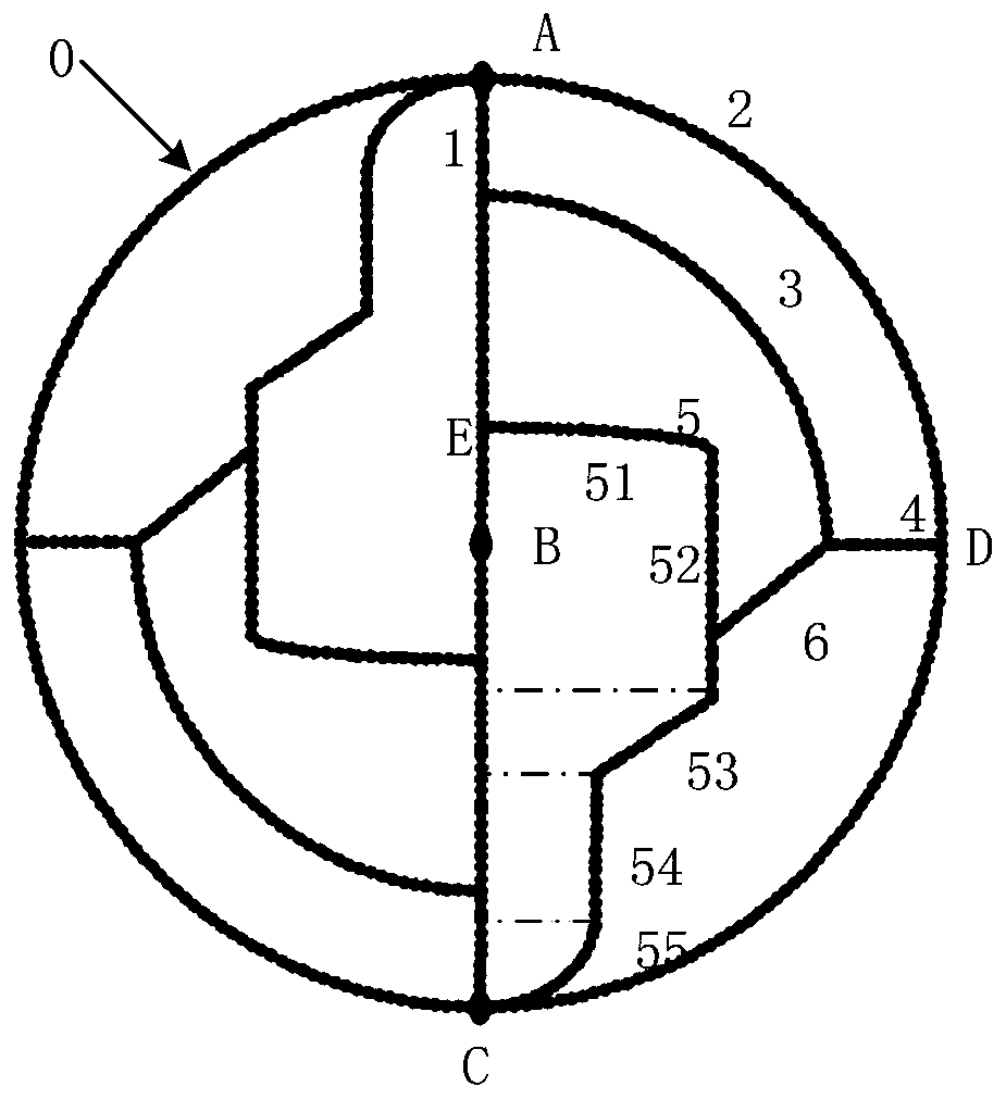
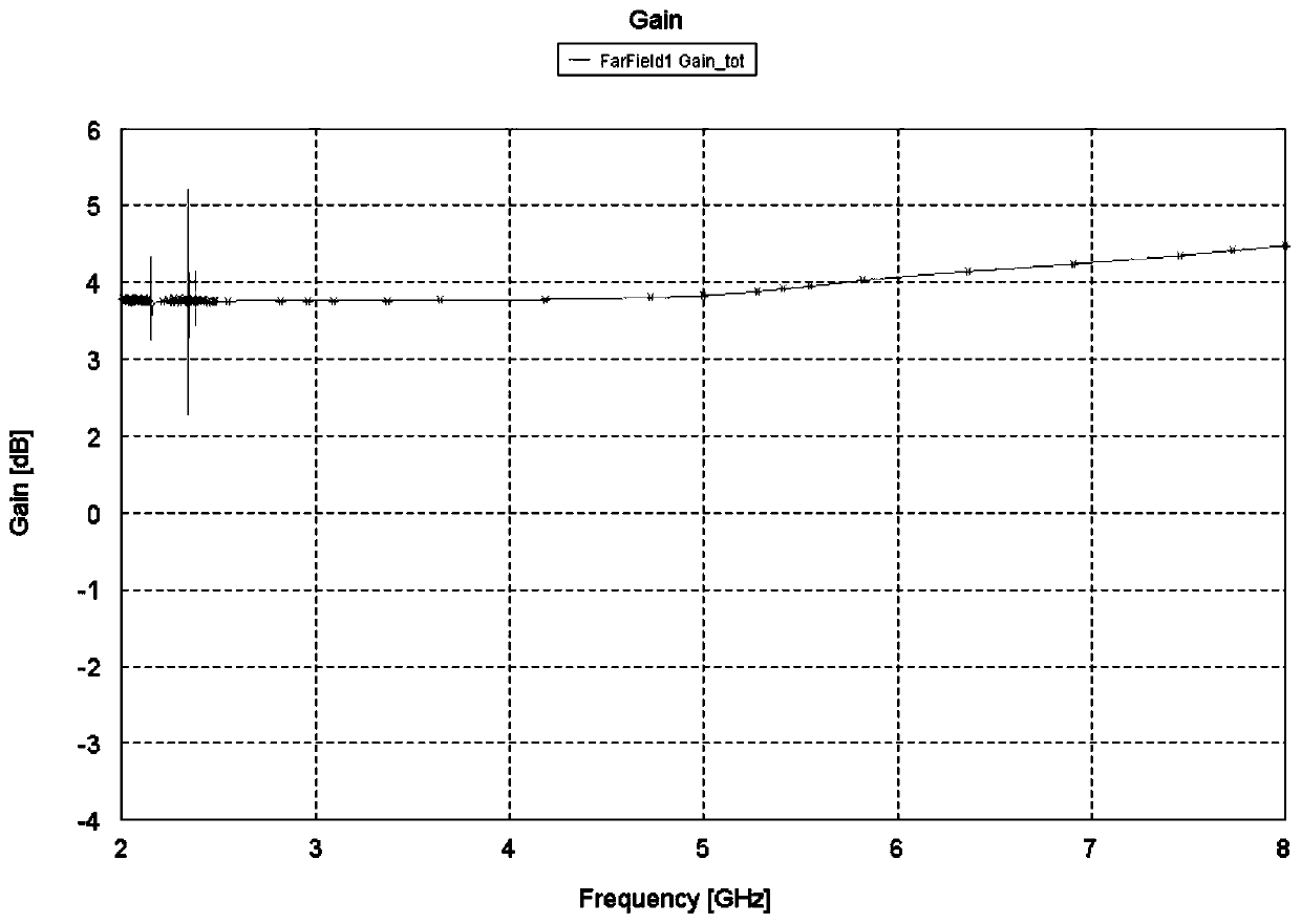
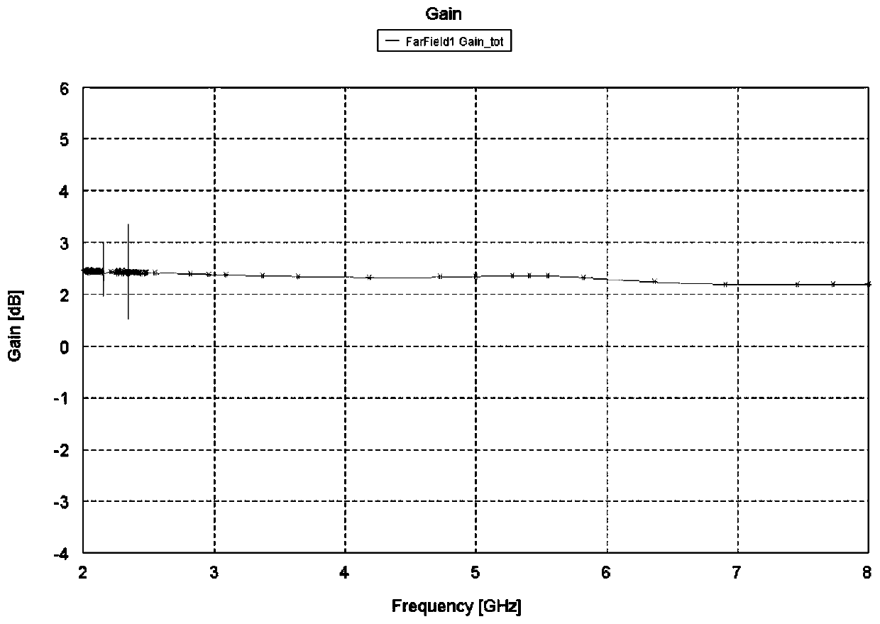
[0027] An embodiment of the present invention provides a high-gain ultra-wideband directional antenna with a symmetrical structure around the center of a circle, such as figure 1 As shown, the directional antenna includes: a circular metal pattern 0 that is symmetrical to the center of the circle and three feeding points A, B, and C that are locat...


PUM


Abstract

The invention relates to a high-gain ultra-wideband directional antenna of an origin symmetric structure. The directional antenna comprises an original-symmetric round metal pattern and three feed points, wherein the three feed points are respectively located at the center and two ends of the round metal pattern; the diameters of the three feed points are superposed with a symmetric axis of the round metal pattern; and the directional antenna is used for transmitting or receiving electromagnetic wave signals from 2.5GHz to 8GHz. The directional antenna can select different frequency bands, avoid the conditions of strong interference and severe channels, and transmit communication signals with high gain.

Description

technical field [0001] The invention relates to the technical field of wireless communication, in particular to a high-gain ultra-wideband directional antenna with a symmetrical structure around the center of a circle. Background technique [0002] Directional antenna refers to an antenna that transmits and receives electromagnetic waves particularly strongly in one or several specific directions, while transmitting and receiving electromagnetic waves in other directions is zero or extremely small. The purpose of using a directional antenna is to increase the effective utilization of radiation power, increase confidentiality, or enhance signal strength to increase anti-interference ability. [0003] In practical applications, the channel condition of the directional antenna is relatively bad due to the strong interference in the environment, which leads to the decrease of the gain of the directional antenna and affects the use. Contents of the invention [0004] Aiming at...

Claims


Application Information

Patent Timeline
Patent Type & Authority Patents(China)
IPC IPC(8): H01Q1/38H01Q1/50
CPCH01Q1/38H01Q1/50
Inventor 谢鹏浩成媛马立云褚杰袁建生秦博宇周宏威王平平
Owner PEOPLES LIBERATION ARMY ORDNANCE ENG COLLEGE
Learn More