Transmission crank

A crank and curved surface technology, applied in the field of transmission cranks, can solve the problems of simple structure, low strength, and inconvenient installation of transmission cranks, and achieve the effects of simple processing technology, reduced processing technology, and weakened torque

Pending Publication Date: 2017-05-10
JIANGSU DATANG MACHINERY
View PDF8 Cites 1 Cited by
  • Summary
  • Abstract
  • Description
  • Claims
  • Application Information

AI Technical Summary

Problems solved by technology

[0002] Pneumatic air valves (sometimes referred to as butterfly valves) in gas turbine engines typically include a coupling system, the actuator portion of which is cantilevered from the valve body to maintain a light weight and simple construction, and the coupling system is used to The translational axial movement of the piston is converted into the rotation of the disc to open or close the valve. The coupling system in a pneumatic air valve usually consists of two main parts: the crank and the connecting rod. The crank and connecting rod are pinned together with a tight fit metal pin. Taken together, the crank can resemble a tuning fork-like structure with a sleeve and two extension arms to connect above and below the connecting rod. To save weight, the crank is also made of carbon fiber, titanium alloy, or aluminum alloy. Due to the material It is more expensive and increases the cost. Due to the simple structure of the existing transmission crank, the strength is not high, and it is inconvenient to install when connecting

Method used


Image

  • Transmission crank
  • Transmission crank
  • Transmission crank

Examples


Embodiment Construction

[0021] The following will clearly and completely describe the technical solutions in the embodiments of the present invention with reference to the accompanying drawings in the embodiments of the present invention. Obviously, the described embodiments are only some, not all, embodiments of the present invention. Based on the embodiments of the present invention, all other embodiments obtained by persons of ordinary skill in the art without making creative efforts belong to the protection scope of the present invention.

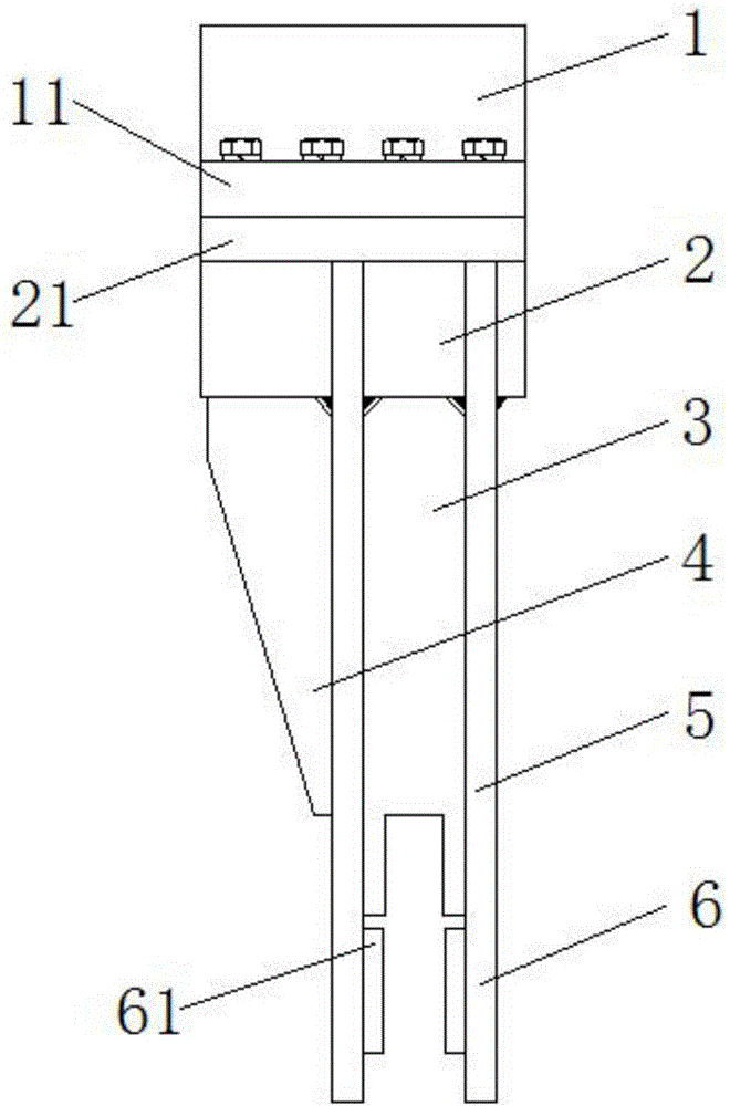
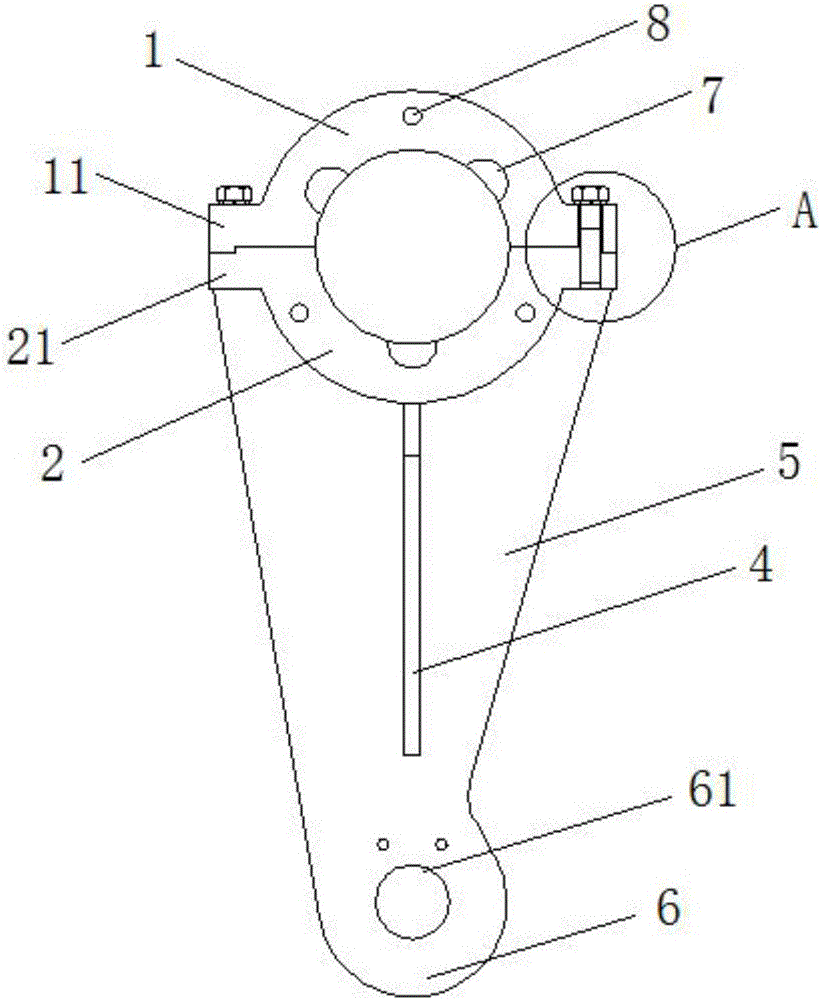
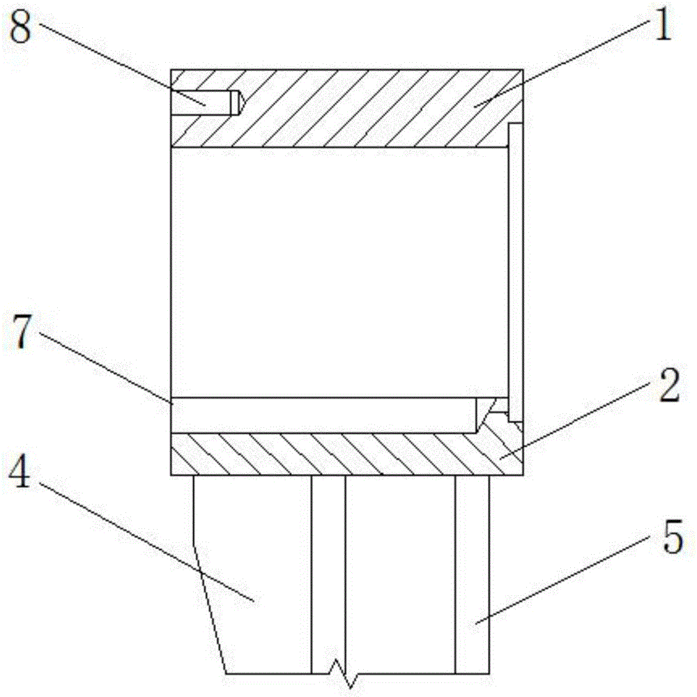
[0022] see Figure 1-6 , the present invention provides a technical solution: a transmission crank, including an upper shell 1 and a lower shell 2, the upper shell 1 and the middle of the front end faces of the lower shell 2 are evenly provided with threaded holes 8, the upper shell 1 and the lower shell 2 The inner side wall of the lower shell 2 is evenly provided with positioning grooves 7, the upper shell 1 and the lower shell 2 are both arc-shaped shell pl...


PUM


Abstract

The invention discloses a transmission crank which comprises an upper casing and a lower casing, wherein an upper ear plate and a lower ear plate are arranged on the end faces of the two horizontal sides of the upper and lower casings respectively. The transmission crank is simple and reliable in structure; the upper and lower casings are connected through bolts, so that a machining process for forging is reduced; by positioning slots, stability in connection with a fixed rod is ensured; a support structure welded by a first vertical plate, a rib plate and second vertical plates is high in stability and material-saving, the mass of the transmission crank is reduced, and meanwhile, the strength of the crank and stability during connection with a connecting rod are also ensured; by the rib plate, radial internal stress on the lower casing is effectively dispersed, and the front ends of the upper and lower casings are prevented from being cracked; by design of extending plates and notches, fit between the upper and lower casings is ensured, and meanwhile, torque on the bolts during rotation is weakened; the machining process is simple, the transmission crank can be rapidly produced in batches, and the strong-strength crank connecting rod application requirement can be met.

Description

technical field [0001] The invention relates to the technical field of transmission cranks, in particular to a transmission crank. Background technique [0002] Pneumatic air valves (sometimes referred to as butterfly valves) in gas turbine engines typically include a coupling system, the actuator portion of which is cantilevered from the valve body to maintain a light weight and simple construction, and the coupling system is used to The translational axial movement of the piston is converted into the rotation of the disc to open or close the valve. The coupling system in a pneumatic air valve usually consists of two main parts: the crank and the connecting rod. The crank and connecting rod are pinned together with a tight fit metal pin. Taken together, the crank can resemble a tuning fork-like structure with a sleeve and two extension arms to connect above and below the connecting rod. To save weight, the crank is also made of carbon fiber, titanium alloy, or aluminum allo...

Claims


Application Information

Patent Timeline
IPC IPC(8): F16C3/22
CPCF16C3/22F16C2361/91
Inventor 唐浩
Owner JIANGSU DATANG MACHINERY
Why Eureka
Try Eureka