
An improved pay-off frame structure

A pay-off stand, an improved technology, is applied in the manufacture of electrical components, circuits, cables/conductors, etc. It can solve the problems of poor outlet, more scratches on cables, and cable quality problems, and achieves simple and reliable structure, Ensuring a clean environment

Active Publication Date: 2018-05-15
GOLD CUP ELECTRIC APP HENGYANG CABLES
View PDF3 Cites 0 Cited by
  • Summary
  • Abstract
  • Description
  • Claims
  • Application Information

AI Technical Summary

Problems solved by technology

For example, for 40-coil barrel-type pay-off racks, double-discharge wire racks are used, and 10-coil barrel-type pay-off racks are arranged in parallel in each row. There is a collection of steering guide wheels, the wires are not smooth, and there are many scratches on the cables, and they do not have the function of storing wires. In this way, when the wires are broken at the upper wire or the remaining wires are insufficient, the wire ends will be pulled into the inside of the rolling machine, resulting in cable quality problem

Method used


Image

  • An improved pay-off frame structure
  • An improved pay-off frame structure
  • An improved pay-off frame structure

Examples

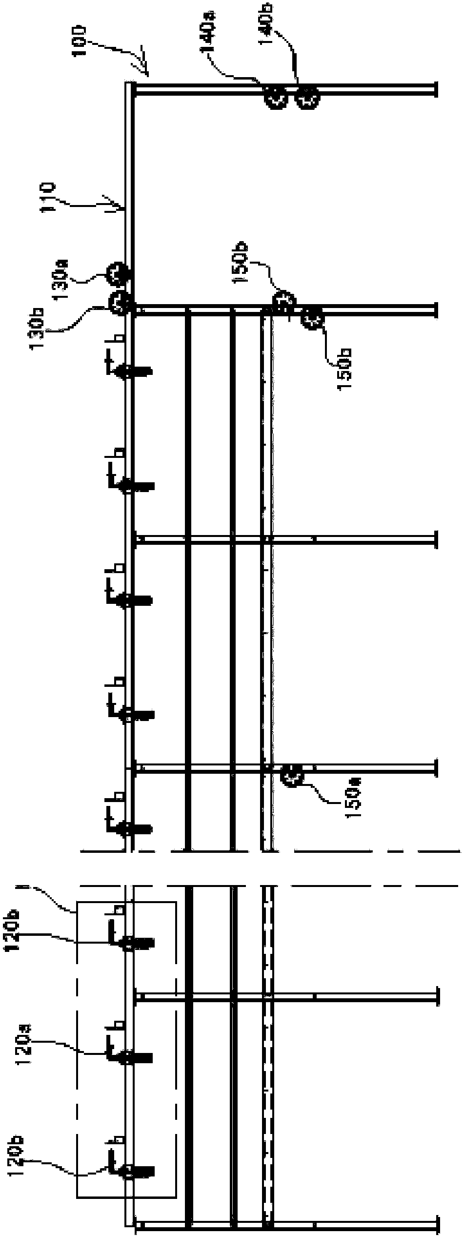
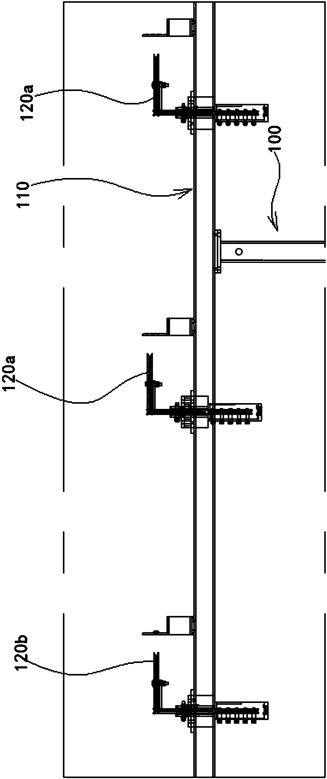

Embodiment Construction

[0026] In order to make the technical means, creative features, objectives and effects achieved by the present invention easy to understand, the present invention will be further elaborated below.

[0027] see Figure 1 to Figure 7 An improved pay-off frame structure shown includes a long pay-off frame 100 extending along the pay-off direction, and installation beams 110 are arranged on the tops of both sides of the long pay-off frame 100 along the length direction, and each installation beam 110 has an upper edge A number of high guide wheels 120a and low guide wheels 120b are arranged at staggered intervals in the length direction. Ten high guide wheels 120a and ten low guide wheels 120b are arranged at staggered intervals along the length direction on each mounting beam 110 in this embodiment, and the high guide wheels 120a and low guide wheels 120b are arranged horizontally, and the high guide wheels 120a The height is higher than that of the low guide wheel 120b. This e...


PUM


Abstract

The invention discloses an improved cable holder structure, which comprises a long cable holder extending in a cable laying direction. Mounting beams are disposed at the two sides of the top of the long cable holder in the length direction. Each mounting beam is equipped with a plurality of high cable guide wheels and low cable guide wheels which cross each other at intervals in the length direction. The front end of each mounting beam is provided with an upper directive wheel and a lower directive wheel. The forefront end of the long cable holder is equipped with a pair of upper directive wheels and a pair of lower directive wheels. The middle portion of the long cable holder is provided with a pair of cable storing guide wheels and a pair of cable storing directive wheels. Cables passing by the high cable guide wheels and the low cable guide wheels are arranged to be an upper layer of cables and a lower layer of cables.

Description

technical field [0001] The invention relates to the field of wire and cable production equipment, in particular to an improved pay-off frame structure. Background technique [0002] At present, domestic aluminum alloy rolling and stranding machines are mainly imported from abroad, and the imported rolling and stranding machines are used to carry out profiled wire stranding on multi-disc barrel type pay-off frames. For example, for 40-coil barrel-type pay-off racks, double-discharge wire racks are used, and 10-coil barrel-type pay-off racks are arranged in parallel in each row. There is a collection of steering guide wheels, the wires are not smooth, and there are many scratches on the cables, and they do not have the function of storing wires. In this way, when the wires are broken at the upper wire or the remaining wires are insufficient, the wire ends will be pulled into the inside of the rolling machine, resulting in Cable quality problem. Contents of the invention ...

Claims


Application Information

Patent Timeline
Patent Type & Authority Patents(China)
IPC IPC(8): H01B13/02
CPCH01B13/0207H01B13/0264
Inventor 杨志强梁根文
Owner GOLD CUP ELECTRIC APP HENGYANG CABLES
Learn More