
cotton mop

A collodion mop and collodion technology, which is applied in the direction of cleaning carpets, floors, household appliances, etc., can solve the problems of poor mopping effect, easy shaking, and inability to adjust the elasticity of the collodion mop head, so as to improve efficiency and achieve good stability. Performance, easy to replace the effect of the collodion head

Active Publication Date: 2019-05-10
JIAXING JACKSON TRAVEL PROD CO LTD
View PDF5 Cites 4 Cited by
  • Summary
  • Abstract
  • Description
  • Claims
  • Application Information

AI Technical Summary

Problems solved by technology

[0003] The disadvantage of the existing collodion mop is that after long-term use, the squeeze roller of the collodion mop cannot be tightly contacted with the collodion head, and there will be a gap between the two, which will cause the collodion head to be damaged during the use of the mop. Unsteady fixation and easy shaking occur, and the floor mopping effect is poor. The collodion mop in the prior art cannot adjust the tightness of the collodion mop head

Method used


Image

  • cotton mop
  • cotton mop
  • cotton mop

Examples


Embodiment 1

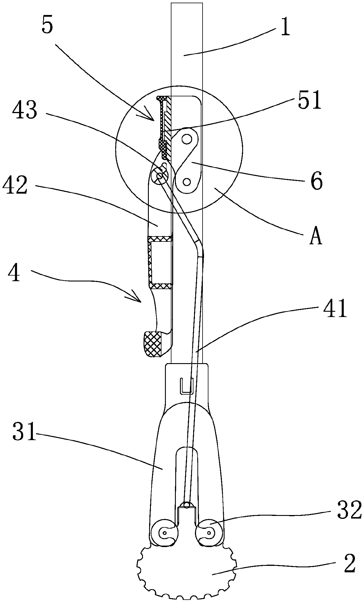
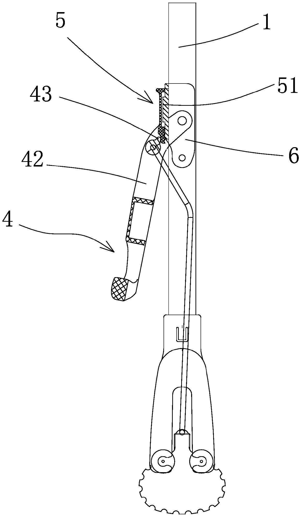
[0040] Such as Figure 1 to Figure 13 As shown, the present embodiment includes a mop rod 1 and a collodion head 2, a water squeeze frame 31 is provided at one end of the mop rod 1, and a water squeeze structure is arranged on the water squeeze frame 31, and the collodion head 2 is located below the water squeeze structure , the collodion head 2 is connected with a control mechanism 4 that can drive the collodion head 2 to move relative to the water-squeezing structure and can position the collodion head 2. Finally, the position of the collodion head 2 relative to the water squeezing structure can be adjusted so that the upper part of the collodion head 2 abuts against the water squeezing structure to adjust the adjustment mechanism 5 for the tightness of the collodion head 2. The degree of tightness between the cotton head 2 and the squeeze roller 32 can be adjusted easily when the collodion head 2 becomes loose, so as to ensure that the collodion head 2 and the squeeze rolle...

Embodiment 2

[0056] Such as Figure 14 As shown, the adjustment mechanism 5 in this embodiment is arranged between the wrench 42 and the mop rod 1, and the adjustment mechanism 5 can adjust the position of the connection between the inner end of the wrench 42 and the mop rod 1 relative to the axial direction of the mop rod 1 so as to realize the collodion Head 2 tightness adjustment.

[0057] Specifically, the adjustment mechanism 5 includes a moving seat 8 that is arranged on the mop rod 1 and can move axially relative to the mop rod 1. The inner end of the wrench 42 is hinged with the moving seat 8. , the rotating sleeve 9 is connected with the moving seat 8 for axial positioning and circumferential rotation.

[0058] In order to facilitate the replacement of the collodion head 2, the collodion head 2 is connected to the pull rod 41 through a detachable structure 7, and the rotating sleeve 9 can drive the collodion head 2 to move up and down relative to the squeezing structure through t...


PUM


Abstract

The invention provides a collodion mop, which comprises a mop rod and a collodion head, wherein one end of the mop rod is provided with a water squeezing frame; a water squeezing structure is arranged on the water squeezing frame; the collodion head is positioned under the water squeezing structure; an operation and control mechanism capable of driving the collodion head to move relative to the water squeezing structure and capable of positioning the collodion head is connected onto the collodion head; and a regulating mechanism is arranged on the operation and control mechanism, and can be used for regulating the position of the collodion head relative to the water squeezing structure after the collodion head is positioned so that the upper part of the collodion head is abutted against the water squeezing structure, and the tightness of the collodion head can be regulated. The collodion mop has the advantage that the tightness between the collodion head and a water squeezing assembly can be regulated.

Description

technical field [0001] The invention belongs to the technical field of cleaning supplies and relates to a mop, in particular to a collodion mop. Background technique [0002] The existing collodion mop comprises a mop bar, a collodion head, a pull bar for pulling the collodion head, and a wrench for pulling the pull bar. On the mop rod, the upper end of the collodion head is located between two water squeezing rollers, the water squeezing rollers are installed on the water squeezing frame, and the water squeezing frame is installed at the end of the mop rod. Pull the pull rod during operation, the collodion head can be pulled upwards, so that the collodion head can squeeze out the water contained in it through the squeezing roller. [0003] The disadvantage of the existing collodion mop is that after long-term use, the squeeze roller of the collodion mop cannot be tightly contacted with the collodion head, and there will be a gap between the two, which will cause the collod...

Claims


Application Information

Patent Timeline
Patent Type & Authority Patents(China)
IPC IPC(8): A47L13/144A47L13/24A47L13/42
CPCA47L13/144A47L13/24A47L13/42
Inventor 张巨鸿宋潘维
Owner JIAXING JACKSON TRAVEL PROD CO LTD
Learn More