A Bidirectional Installable Hidden Door Closer

A technology of door closers and rotating arms, applied in the field of hidden door closers, which can solve the problems of poor running stability, stagnation, and increased production costs of door closers, and achieve the effects of reducing production costs and simple installation

Active Publication Date: 2018-05-11
SHANGHAI YANGYANG DADUOLI HARDWARE PROD CO LTD
View PDF8 Cites 0 Cited by
  • Summary
  • Abstract
  • Description
  • Claims
  • Application Information

AI Technical Summary

Problems solved by technology

At present, there are many types of door closers, most of which have the problem of poor running stability, and are prone to jamming during operation
Moreover, current door closers can generally only be installed from one direction, and separate designs are required for doors that open from different directions (left or right), which will inevitably increase production costs

Method used


Image

  • A Bidirectional Installable Hidden Door Closer
  • A Bidirectional Installable Hidden Door Closer
  • A Bidirectional Installable Hidden Door Closer

Examples


Embodiment 1

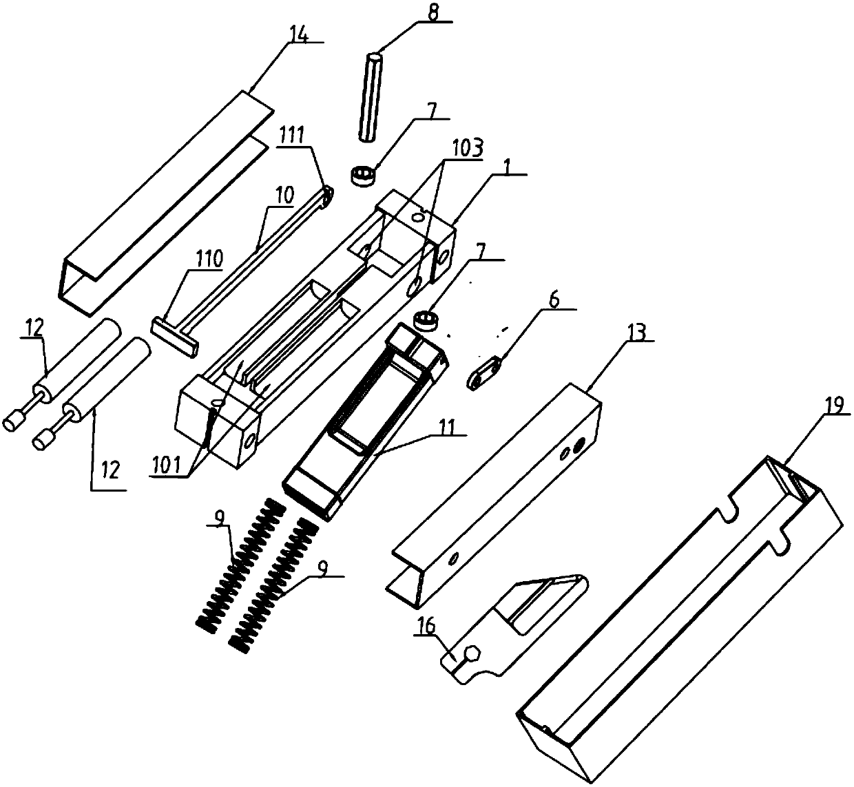
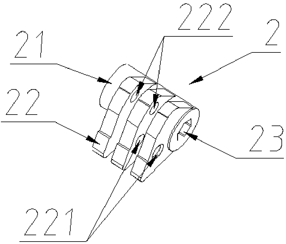
[0032] Such as Figure 1-6 The shown door closer includes a main body 1, two oil cylinder grooves 101 are arranged on one side of the main body 1, and an oil cylinder 12 is respectively placed in each oil cylinder groove 101, and the cylinder barrel of the oil cylinder 12 abuts against At the bottom of the cylinder tank 101. Inside the main body 1 and on the back of the oil cylinder groove 101, a slider 11 that slides back and forth along the length direction of the main body 1 is provided. The sliding direction of the slider 11 is parallel to the moving direction of the oil cylinder 12. A rotating member 2 is provided at the same end as the oil cylinder 12 , and the rotating member 2 is rotatably mounted on the main body 1 through a rotating rod 8 . The slider 11 is connected to the rotating member 2, and the slider 11 is provided with a spring 9 at an end far away from the rotating member 2, and one end of the spring 9 abuts against the slider 11, and the other end abuts ag...

Embodiment 2

[0044] The difference between the second embodiment and the first embodiment lies in the rotating arm and the positioning block, and the rest of the structures are exactly the same. The rotating arm 116 in this embodiment is a bent rod, and when no external force is applied, the end of the rotating arm 116 away from the rotating rod 8 protrudes to the front of the door panel and extends in the width direction of the door panel. Similarly, when the installation directions are inconsistent, the rotating arm 116 needs to be replaced, and the structures of the rotating arm 116 in the two cases are mirror images of each other.

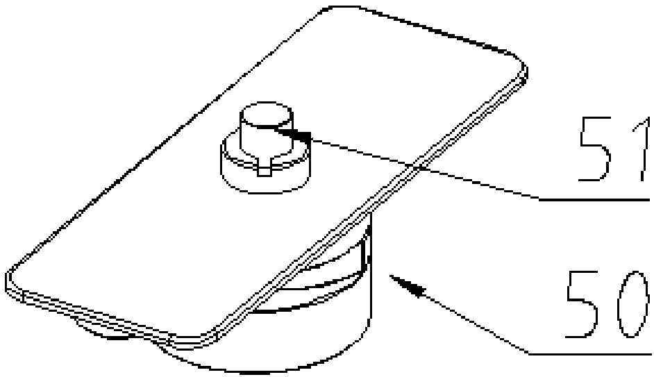
[0045] Such as Figure 12-15 As shown, the positioning block 150 of this embodiment includes a housing 151, a core 152 and a fixed plate 153, a gap 1511 is provided in the middle of the housing 151, and a movable moving plate is provided on the core 152 1521, such as Figure 14 with 15 As shown, the notch 1511 cooperates with the moving plate 1521 to for...


PUM


Abstract

The invention discloses a hidden type door closer capable of achieving bidirectional installation. The hidden type door closer capable of achieving bidirectional installation comprises a body, a rotating piece, a rotating arm, a rotating rod, a resetting structure, a damping structure and a locating block. The rotating piece and the rotating arm are rotationally installed on the body through the rotating rod. The rotating arm is installed on the portion, extending out from the body, of the rotating rod. The resetting structure and the damping structure are arranged in the body and connected with the rotating piece. The resetting structure generates pull force on the rotating piece all the time. The damping structure generates push force on the rotating piece all the time. The pull force is always larger than the push force. The locating block is connected with the rotating arm in a sliding manner. The rotating rod can extend out from the different sides of the body. The structures of the rotating arm installed on the different sides of the body are different. The hidden type door closer can be installed in a bidirectional lanner, and the production cost is effectively reduced.

Description

technical field [0001] The invention relates to a door closer, in particular to a bidirectionally installed concealed door closer. Background technique [0002] Door closers are mainly used in commercial and public buildings, and are also used in housing. The main function of the door closer is to realize the self-closing of the door without violent collision with the door frame. At present, there are various types of door closers, most of which have the problem of poor running stability, and are prone to jamming during operation. Moreover, the current door closers generally can only be installed from one direction, and separate designs are required for doors opened from different directions (left or right), which will inevitably increase production costs. Contents of the invention [0003] The main purpose of the present invention is to provide a concealed door closer that can be installed in two directions, which can be installed in two directions, and can be installed ...

Claims


Application Information

Patent Timeline
Patent Type & Authority Patents(China)
IPC IPC(8): E05F15/56E05F5/08
CPCE05F5/08E05F15/56
Inventor 太田益大
Owner SHANGHAI YANGYANG DADUOLI HARDWARE PROD CO LTD
Why Eureka
Try Eureka