Mechanical logic device, mechanical digital password input device with mechanical logic device, and digital password lock
A technology of mechanical logic and input device, which is applied in combination locks, building locks, sign-checking locks, etc., can solve the problems that the number of mixed double-bit devices cannot be adjusted, and the logic function cannot be adjusted, so as to save space, The effect of expanding the amount of keys, memory and easy operation
- Summary
- Abstract
- Description
- Claims
- Application Information
AI Technical Summary
Problems solved by technology
Method used
Image
Examples
Embodiment 1
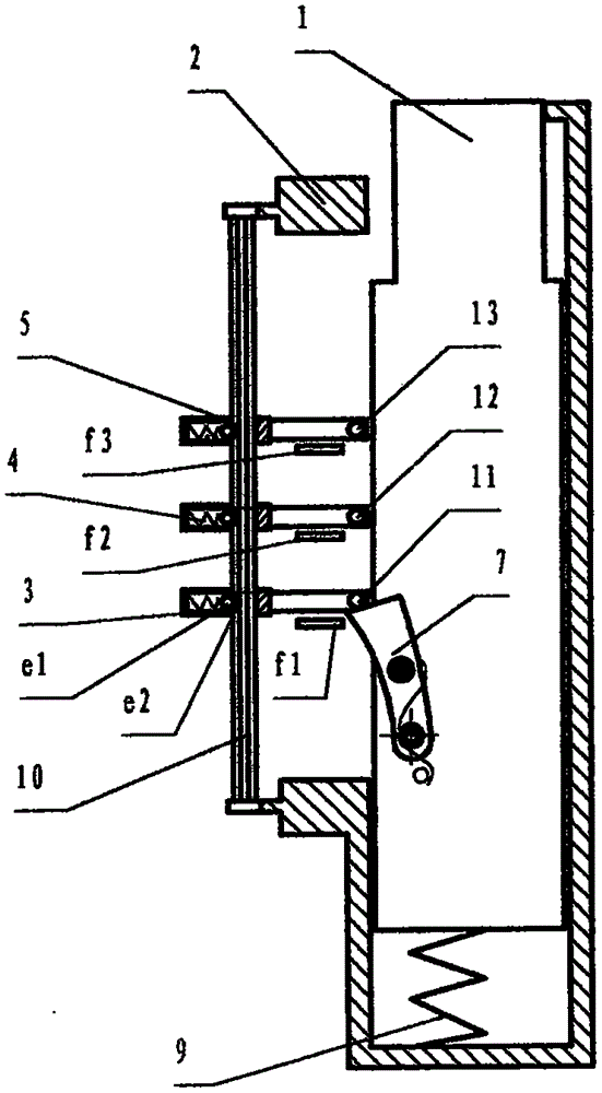
[0029] Fig. 1 is the schematic diagram of mechanical logic device of the present invention, and this mechanical logic device comprises a mixed double-bit device, and described mixed double-bit device comprises housing 2, and movable part cylinder 1 is arranged in described housing, and described movable part It can move between the reset position and the set position in the housing, and also includes a combined locking mechanism. The combined locking mechanism has 3 locking mechanisms, so that the movable parts can be locked in sequence at 3 positions including the reset position, The locking mechanism is composed of two components, that is, the locking mechanism 7 and the locking pins 11-13 on the movable part 1, that is, the mixed double-position device has 3 positions, and the input ends of each locking mechanism have independently arranged input ends. f1-f3, housing 2 is provided with positioning seat 3-5, the positioning seat is positioned on the shape shaft 10 by the spri...
Embodiment 2
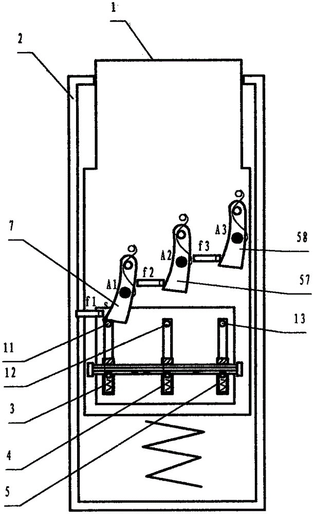
[0031] figure 2 It is another form of the mechanical logic device in Fig. 1. The difference from Fig. 1 is that the movable assembly with the positioning seat 3-5 is set on the movable part 1, and the locking pins 11-13 on the positioning seat are scattered , and three locking mechanisms 7, 57, 58 are correspondingly set on the housing 2, and the force input ends f1-f3 of each locking mechanism are independently set.
Embodiment 3
[0033] Figure 3a It is another form of the mechanical logic device as shown in Figure 1. The difference from Figure 1 is that the pin spring locking mechanism 17 is set on the movable part, and the positioning seat 3-5 is also set on the housing 2, and the positioning seat extends The pins set at the ends are triangular blocks 14-16, and independent power input ends f1-f3 are set; Figure 3b It is another schematic diagram of the shifting mechanism, Figure 3c yes Figure 3b In the left view of the left side view, a guide shaft B parallel to the shape axis 10 is set on the housing 2, and a fork 18 is set on the guide shaft. The upper axis moves, and when the fork moves up, the positioning seat 5 is blocked, and the lower end of the fork also has a slot e7; the elevating rod 20 is arranged in the slot e4 of the bracket 2, and the fork top of the elevating rod is also rotated in the groove. There is a projection on the top to be stuck in the slot e7, which can drive the fork...
PUM
 Abstract
Description
Claims
Application Information
 - R&D
- Intellectual Property
- Life Sciences
- Materials
- Tech Scout
- Unparalleled Data Quality
- Higher Quality Content
- 60% Fewer Hallucinations
Browse by: Latest US Patents, China's latest patents, Technical Efficacy Thesaurus, Application Domain, Technology Topic, Popular Technical Reports.
© 2025 PatSnap. All rights reserved.Legal|Privacy policy|Modern Slavery Act Transparency Statement|Sitemap|About US| Contact US: help@patsnap.com


