
A clamping and supporting device for a distribution box partition

A support device and distribution box technology, applied in the direction of auxiliary devices, auxiliary welding equipment, welding/cutting auxiliary equipment, etc., can solve the problems of poor stable support effect, low work efficiency, poor clamping effect, etc., and achieve high work efficiency , Fast installation and easy operation

Inactive Publication Date: 2018-01-23
淄博凯越电气有限公司
View PDF5 Cites 0 Cited by
  • Summary
  • Abstract
  • Description
  • Claims
  • Application Information

AI Technical Summary

Problems solved by technology

[0003] In order to solve the above problems, the present invention provides a clamping and supporting device for the partition of the distribution box, which can solve the problems of complex operation, high labor intensity, manual positioning and clamping, slow installation speed, and problems in the existing processing method of the partition of the distribution box. Problems such as poor clamping effect, poor stable support effect and low work efficiency can realize the stable clamping and supporting function of the distribution box partition, easy to operate, no manual operation, no manual positioning and clamping, fast installation speed, clamping Good effect, good stable support effect and high work efficiency

Method used


Image

  • A clamping and supporting device for a distribution box partition
  • A clamping and supporting device for a distribution box partition
  • A clamping and supporting device for a distribution box partition

Examples


Embodiment Construction

[0014] In order to make the technical means, creative features, goals and effects achieved by the present invention easy to understand, the present invention will be further described below in conjunction with specific illustrations.

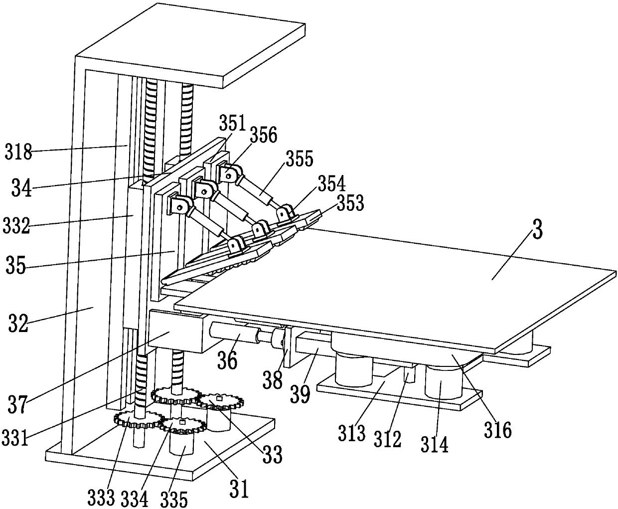
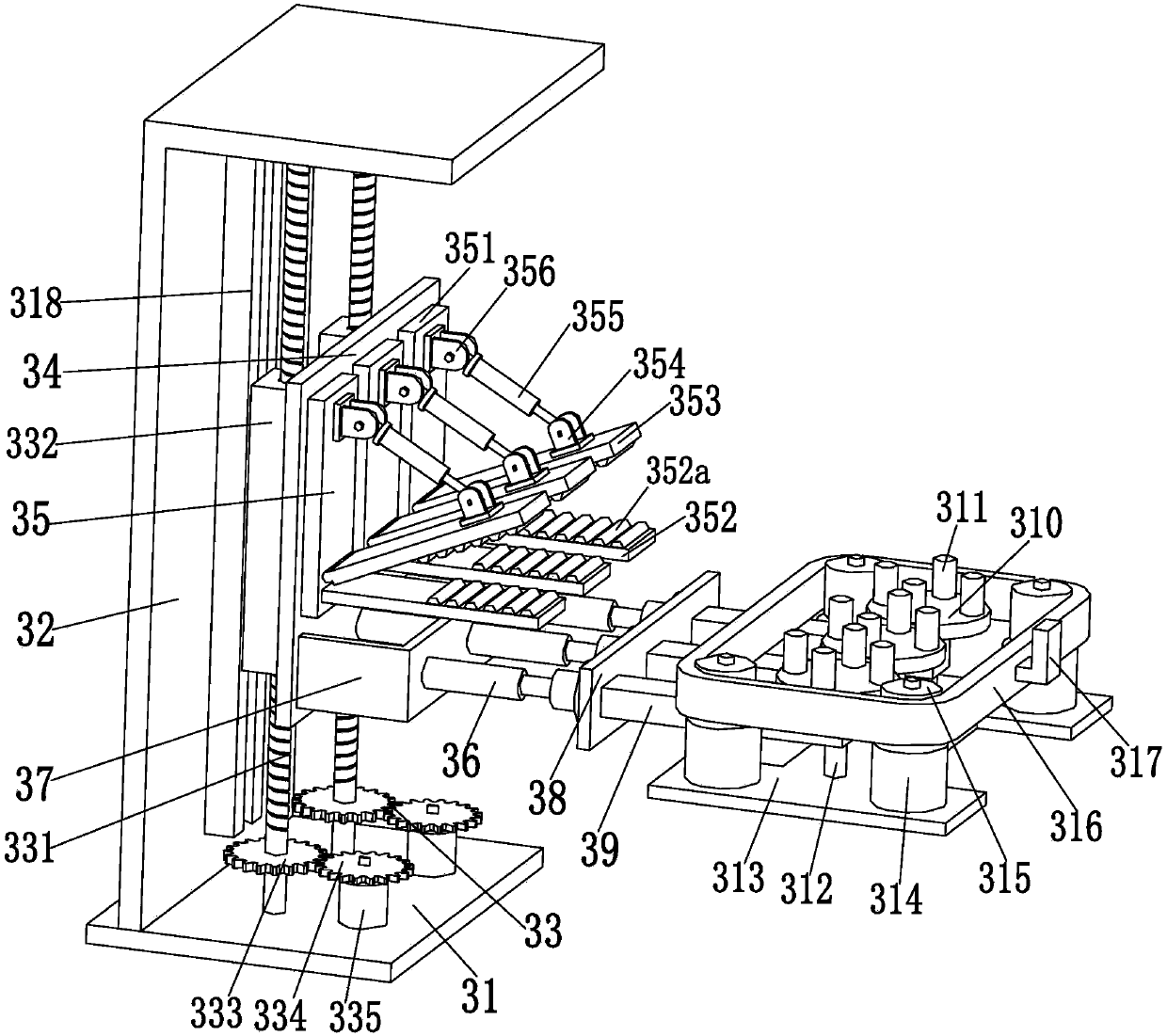
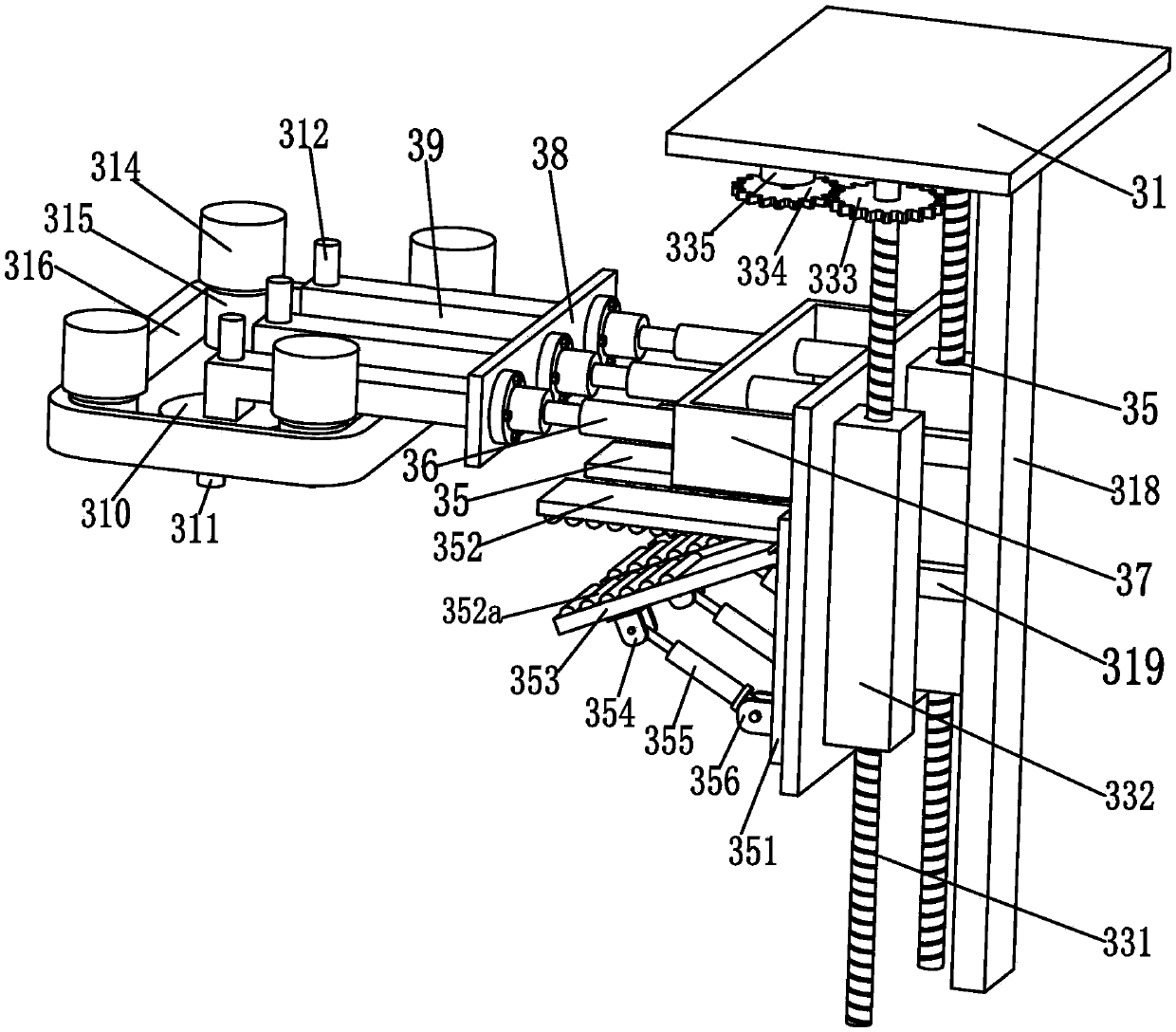
[0015] like Figure 1 to Figure 3As shown, a clamping and supporting device for a distribution box partition includes a bottom plate 31, an L-shaped bracket 32 ​​is welded on the upper end surface of the bottom plate 31, and two lifting transmission mechanisms 33 are symmetrically installed on the upper end surface of the bottom plate 31. The top of a lifting transmission mechanism 33 is installed on the upper end lower side of the L-shaped support 32 through bearings, and the lifting plate 34 is installed on the two lifting transmission mechanisms 33, and the lifting plate 34 is driven by the two lifting transmission mechanisms 33 for stable lifting movement, thereby The installation height of the partition body 3 can be adjusted. Three clampin...


PUM


Abstract

The invention relates to a distribution-box partition plate clamping and supporting device which comprises a base plate. An L-shaped support is welded to the upper end face of the base plate, two lifting transmission mechanisms are symmetrically installed on the upper end face of the base plate, the top end of each lifting transmission mechanism is installed on the lower side face of the upper end of the L-shaped support through a bearing, a lifting plate is installed on the two lifting transmission mechanisms, the lifting plate is driven by the two lifting transmission mechanisms to do stable lifting motion, and therefore installation height of a partition plate body can be adjusted; three clamping mechanisms are evenly installed on the side wall of the lifting plate, and the partition plate body is clamped by the three clamping mechanism; and due to the fact that the three clamping mechanisms are evenly distributed on the lifting plate, the partition plate body can be stably clamped through the three evenly distributed clamping mechanisms. According to the distribution-box partition plate clamping and supporting device, stable clamping and supporting functions on a distribution-box partition plate can be achieved, operation is easy and convenient, manual operation is not needed, and the distribution-box partition plate clamping and supporting device has the advantages of being free of manual positioning clamping, high in installation speed, good in clamping effect, good in stable supporting effect, high in working efficiency and the like.

Description

technical field [0001] The invention relates to the technical field of distribution boxes, in particular to a clamping and supporting device for a partition of a distribution box. Background technique [0002] The distribution box is a kind of electrical equipment, which is the general control center of various electrical appliances. It provides protection, monitoring and control for various electrical appliances. It is also an indispensable power distribution auxiliary equipment for automatic production. Busbar, zero busbar, grounding busbar and electrical components and other components, and the box body includes partitions, sealing plates, left and right side panels, bottom plate, top plate, door, rings and nameplates, etc., among which the box body is the most important component Parts, while the partition is mainly to divide the box into blocks and layers, which is convenient for the modularized and layered installation of the original electrical components. The existin...

Claims


Application Information

Patent Timeline
Patent Type & Authority Patents(China)
IPC IPC(8): B23K37/04
CPCB23K37/04B23K37/0443
Inventor 于修宽王兆兴于凯刘永喜李涛
Owner 淄博凯越电气有限公司
Learn More