Blade set, hair cutting appliance, and related manufacturing method

一种毛发切割、刀片组的技术,应用在电操作毛发切割器具,制造用于毛发切割器具的固定刀片和刀片组,固定刀片领域,能够解决不舒服、引导准确度切割准确度降低、不是很人性化等问题

Active Publication Date: 2017-03-01
KONINKLIJKE PHILIPS NV
View PDF5 Cites 4 Cited by
  • Summary
  • Abstract
  • Description
  • Claims
  • Application Information

AI Technical Summary

Problems solved by technology

As a result, a user who desires to both shave and trim his / her body hair may need to purchase and apply two separate appliances
[0010] Furthermore, combined shaving and trimming devices exhibit several disadvantages, since they basically require two sets of cutting blades and corresponding drive mechanisms
As a result, these devices are heavier and more prone to wear than standard type single purpose hair cutting appliances, and also require expensive manufacturing and assembly processes
Similarly, operating these combined devices can often be quite an uncomfortable and complicated experience
Even in the case of using a traditional combination shaving and trimming device comprising two separate cutting parts, operating the device and switching between different modes of operation can be considered time-consuming and not very user-friendly
Since the cutting portions are typically placed at different locations on the device, guidance accuracy (and thus also cutting accuracy) can be reduced as the user needs to get used to the two distinctly different dominant holding positions during operation

Method used


Image

  • Blade set, hair cutting appliance, and related manufacturing method
  • Blade set, hair cutting appliance, and related manufacturing method
  • Blade set, hair cutting appliance, and related manufacturing method

Examples


Embodiment Construction

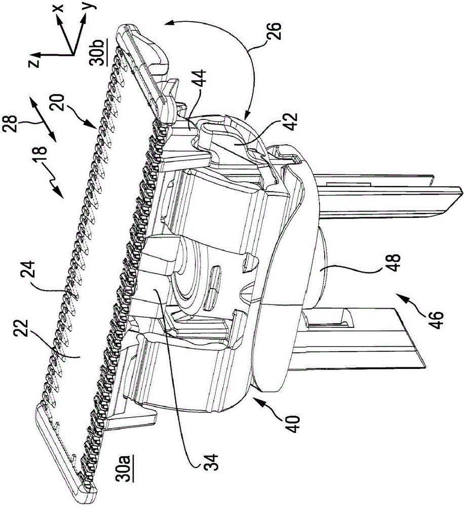
[0093] figure 1 An exemplary embodiment of a hair cutting appliance 10 , in particular an electric hair cutting appliance 10 , is schematically illustrated in a simplified perspective view. Cutting instrument 10 may include a housing or more specifically a housing portion 12, a motor indicated by a dashed box 14 in housing portion 12, and a drive mechanism or drive train indicated by a dashed box 16 in housing portion 12. . To provide power to the motor 14, at least in some embodiments of the cutting instrument 10, an electrical battery, indicated by a dashed box 17 in the housing portion 12, may be provided, such as, for example, a rechargeable battery, a replaceable battery, or the like. However, in some embodiments, the cutting implement 10 may be further provided with a power cable for connection to a power source. A power connector may be provided in addition to or as an alternative to the (internal) power supply battery 17 .

[0094] The cutting implement 10 may furth...


PUM


Abstract

The present disclosure relates to a hair cutting appliance (10),a blade set (20) for a hair cutting appliance (10),and to an integrally formed metal-plastic composite stationary blade (22) for said blade set (20). Said stationary blade (22) may comprise a first wall portion (58) arranged to serve as a skin facing wall when in operation, a second wall portion (60) at least partially offset from the first wall portion (58), such that the first wall portion (58) and the second wall portion (60) define therebetween a guide slot (116) arranged to receive a movable cutter blade (24),at least one toothed leading edge (30) jointly formed by the first wall portion (58) and the second wall portion (60), and a plastic component (114) comprising at least one mounting element (36),wherein the at least one toothed leading edge (30) comprises a plurality of teeth (90),wherein the first wall portion (58) and the second wall portion (60) are integrally made from a metal component (56), particularly from a sheet metal component (56),wherein the first wall portion (58) and the second wall portion (60) mutually define an inner metal shell of the stationary blade (22), and wherein the plastic component (114) is molded to the second wall portion (60).The disclosure further relates to a method for manufacturing a respective blade.

Description

technical field [0001] The present disclosure relates to hair cutting appliances, in particular electrically operated hair cutting appliances, and more particularly to stationary blades for blade sets of such appliances. The blade set may be arranged to move through the hair in a direction of movement to cut the hair. The stationary blade may include a first wall portion and a second wall portion defining a guide slot therebetween in which the movable cutter blade may be at least partially surrounded and guided. The present disclosure further relates to methods for manufacturing stationary blades and blade sets for hair cutting appliances. Background technique [0002] GB 2 266 259 A discloses a hair trimmer for the nose or ears, comprising a body serving as a handle and having an extension for insertion in the nose or ear, the extension having a cutting member at its distal end, so The cutting member includes a reciprocating blade member slidingly engaged with an anvil ha...

Claims


Application Information

Patent Timeline
Patent Type & Authority Applications(China)
IPC IPC(8): B26B19/04B26B19/38
CPCB26B19/042B26B19/3846B26B19/063B26B19/20B26B19/3893
Inventor S·萨布拉特斯钱
Owner KONINKLIJKE PHILIPS NV
Why Eureka
Try Eureka