
Flying car

A flying car and body technology, applied in the field of flying cars, can solve the problems of poor overall aesthetics, increased driving resistance, and large ground state size, and achieve the effects of convenient processing, reduced wingspan length, and simple and easy design.

Active Publication Date: 2017-02-22
BEIHANG UNIV
View PDF5 Cites 6 Cited by
  • Summary
  • Abstract
  • Description
  • Claims
  • Application Information

AI Technical Summary

Problems solved by technology

[0004] The present invention proposes a new flying car design scheme in view of the poor overall aesthetics caused by the exposed flying parts of the existing flying cars, the size of the ground state being larger than that of ordinary cars and the increase in driving resistance

Method used


Image

  • Flying car
  • Flying car
  • Flying car

Examples


Embodiment Construction

[0045] The present invention will be further described in detail below with reference to the drawings and embodiments.

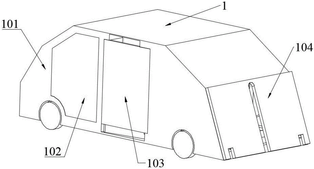
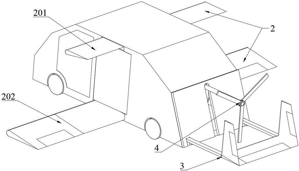
[0046] Such as figure 1 , 2 Shown are the overall schematic diagrams of the flying car of the present invention running on the ground and flying in the air. A flying car of the present invention includes a body 1, a wing 2, a tail 3 and a propeller 4, such as figure 1 , 2 Shown.

[0047] The body 1 includes a body structure 101, a front door 102, a rear door 103 and a trunk cover 104, such as figure 1 As shown, the front door 102, the rear door 103 and the trunk cover 104 are respectively hinged to the vehicle body structure 101;

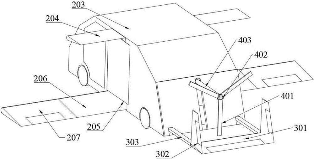
[0048] Wing 2 includes upper wing 201 and lower wing 202 and their variant mechanisms, such as figure 2 As shown, the upper wing 201 and the lower wing 202 are respectively hinged to the vehicle body structure 101; the upper wing 201 is divided into an upper wing inner section 203 and an upper wing outer section 204, and the lower wing 2...


PUM


Abstract

The invention discloses a flying car. The flying car comprises a car body, a wing, an empennage and a propeller, wherein the car body comprises a car body structure, front car doors, rear car doors and a trunk lid; the front car doors, the rear car doors and the trunk lid are hinged to the car body structure respectively; the wing comprises an upper wing and a lower wing and variant mechanisms thereof; the upper wing and the lower wing are hinged to the car body structure respectively; the empennage comprises a horizontal tail, vertical tails and telescopic empennage shafts; one end of each telescopic empennage shaft is fixedly connected with the car body structure, and the other ends of the telescopic empennage shafts are fixedly connected with the wing tips of the horizontal tail and the wing roots of the vertical tails respectively; the propeller comprises propeller blades, a propeller hub and a telescopic propeller shaft; one end of the telescopic propeller shaft is fixedly connected with the car body structure, and the other end of the telescopic propeller shaft is fixedly connected with the propeller hub; the three propeller blades are hinged to the propeller hub respectively. The wing of the flying car adopts a double-wing layout, and under the premise that the total lifting force is ensured, the wingspan length is greatly reduced, so that the wing can be conveniently folded into the car body.

Description

Technical field [0001] The invention relates to the field of flying cars, in particular to a flying car. Background technique [0002] Since the 1940s, automobile and aircraft design technology has become increasingly mature, which has greatly promoted the rapid development of ground transportation and air transportation, and enhanced the convenience of residents' travel. However, with the development of traffic today, problems such as urban traffic jams and inconvenient traffic in remote areas have become increasingly prominent. Thus, the concept of "flying car" came into being. So far, several layout forms of flying cars have been proposed and verified. The fixed-wing flying car is one of the typical layout forms. Its advent and the approval of the flying license make the flying car really come into people's field of vision. In order to make flying cars more compact and maintain high performance on the ground, various forms of folding fixed wings have appeared one after anot...

Claims


Application Information

Patent Timeline
IPC IPC(8): B60F5/02
CPCB60F5/02
Inventor 吴江浩李晗林海英王云鹏
Owner BEIHANG UNIV
Learn More