A dispensing device for electronic components

A technology of electronic components and dispensing devices, which is applied to the device and coating of the surface coating liquid, can solve the problems of poor dispensing effect and low work efficiency, and achieve time saving, firm position and manpower saving Effect

Active Publication Date: 2017-11-10
深圳市怡海智芯科技有限公司
View PDF7 Cites 2 Cited by
  • Summary
  • Abstract
  • Description
  • Claims
  • Application Information

AI Technical Summary

Problems solved by technology

[0005] In order to overcome the dispensing device of the electronic components in the prior art, the present invention cannot accurately align the dispensing points of the electronic components during the dispensing process, resulting in poor dispensing effect and relatively low work efficiency The technical problem to be solved by the present invention is to provide a kind of electronic components with simple operation, convenient use, accurate alignment of dispensing points of electronic components during dispensing, good dispensing effect and high work efficiency. Dispensing device

Method used


Image

  • A dispensing device for electronic components
  • A dispensing device for electronic components
  • A dispensing device for electronic components

Examples


Embodiment 1

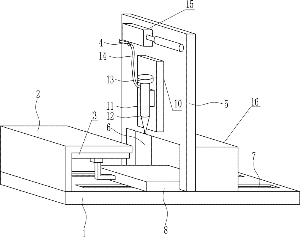
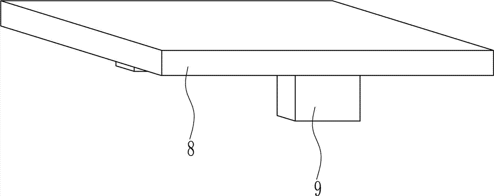
[0038] A dispensing device for electronic components, such as Figure 1-9 As shown, it includes bottom plate 1, L-shaped support plate 2, left and right moving device 3, pressure regulating valve 4, vertical plate 5, placing plate 8, slider 9, up and down moving device 10, glue tube 11, dispensing syringe 12. Cover 13, high-pressure gas pipe 14 and pressure regulating valve 4. L-shaped support plate 2 is welded on the left end of the top of bottom plate 1. Vertical plate 5 is welded vertically in the middle of the top of bottom plate 1. Opening 6 is opened on the lower part of vertical plate 5. On bottom plate 1 A chute 7 is opened front and rear symmetrically, and a slide block 9 is slidably arranged in the chute 7, and the slide block 9 is slidably matched with the chute 7. The top of the slide block 9 is welded with a placement plate 8, and the placement plate 8 is located at the top of the bottom plate 1. The plate 8 cooperates with the opening 6, and the inner horizontal ...

Embodiment 2

[0040] A dispensing device for electronic components, such as Figure 1-9 As shown, it includes bottom plate 1, L-shaped support plate 2, left and right moving device 3, pressure regulating valve 4, vertical plate 5, placing plate 8, slider 9, up and down moving device 10, glue tube 11, dispensing syringe 12. Cover 13, high-pressure gas pipe 14 and pressure regulating valve 4. L-shaped support plate 2 is welded on the left end of the top of bottom plate 1. Vertical plate 5 is welded vertically in the middle of the top of bottom plate 1. Opening 6 is opened on the lower part of vertical plate 5. On bottom plate 1 A chute 7 is opened front and rear symmetrically, and a slide block 9 is slidably arranged in the chute 7, and the slide block 9 is slidably matched with the chute 7. The top of the slide block 9 is welded with a placement plate 8, and the placement plate 8 is located at the top of the bottom plate 1. The plate 8 cooperates with the opening 6, and the inner horizontal ...

Embodiment 3

[0043] A dispensing device for electronic components, such as Figure 1-9 As shown, it includes bottom plate 1, L-shaped support plate 2, left and right moving device 3, pressure regulating valve 4, vertical plate 5, placing plate 8, slider 9, up and down moving device 10, glue tube 11, dispensing syringe 12. Cover 13, high-pressure gas pipe 14 and pressure regulating valve 4. L-shaped support plate 2 is welded on the left end of the top of bottom plate 1. Vertical plate 5 is welded vertically in the middle of the top of bottom plate 1. Opening 6 is opened on the lower part of vertical plate 5. On bottom plate 1 A chute 7 is opened front and rear symmetrically, and a slide block 9 is slidably arranged in the chute 7, and the slide block 9 is slidably matched with the chute 7. The top of the slide block 9 is welded with a placement plate 8, and the placement plate 8 is located at the top of the bottom plate 1. The plate 8 cooperates with the opening 6, and the inner horizontal ...


PUM


Abstract

The invention relates to a gluing device and especially relates to a gluing device for an electronic component. The technical problem to be solved by the invention is to provide the gluing device for the electronic component, which has the advantages of simple operation, convenience in use, capability of accurately aligning with a gluing point of the electronic component in a gluing process, good gluing effect and high working efficiency. For solving the technical problem, the gluing device for the electronic component, provided by the invention, comprises a base plate, an L-shaped support plate, a left and right moving device, a pressure regulating valve, a vertical plate, a loading plate, a slide block, an up and down moving device, a glue filling drum, a gluing needle cylinder and a cover, wherein the L-shaped support plate is welded at the left end of the top of the base plate; the vertical plate is vertically welded in the middle of the top of the base plate; an opening is formed in the lower part of the vertical plate; and slide slots are symmetrically formed in the base plate from front to back. The gluing device for the electronic component, provided by the invention, has the advantages of simple operation, convenience in use and capability of accurately aligning with the gluing point of the electronic component in the gluing process.

Description

technical field [0001] The invention relates to a glue dispensing device, in particular to a glue dispensing device for electronic components. Background technique [0002] Electronic components are components of electronic components and electric small machines and instruments. They are often composed of several parts and can be used in similar products; they often refer to certain parts in industries such as electrical appliances, radios, and instruments, such as capacitors and transistors. The general term for sub-devices such as springs, hairsprings, and springs. Common ones include diodes, etc. Electronic components include: resistors, capacitors, potentiometers, electron tubes, radiators, electromechanical components, connectors, semiconductor discrete devices, electroacoustic devices, laser devices, electronic display devices, optoelectronic devices, sensors, power supplies, switches, micro-motors , electronic transformers, relays, printed circuit boards, integrated...

Claims


Application Information

Patent Timeline
Patent Type & Authority Patents(China)
IPC IPC(8): B05C5/02B05C9/08B05C11/10
CPCB05C5/0208B05C9/08B05C11/1026
Inventor 刘梅香
Owner 深圳市怡海智芯科技有限公司
Why Eureka
Try Eureka