A single-layer rotating stage car

A stage car, single-layer technology, applied in the field of single-layer rotary stage car, can solve the problems of stage instability, poor flatness, affecting performance effects, etc., to achieve diversified performance forms, lower requirements for ground flatness, and adaptability strong effect

Active Publication Date: 2018-11-27
蒙城县东正汽车有限公司
View PDF5 Cites 0 Cited by
  • Summary
  • Abstract
  • Description
  • Claims
  • Application Information

AI Technical Summary

Problems solved by technology

Due to the poor flatness of the ground in mountainous areas, if the height of the supporting legs cannot be adjusted, it will cause the stage to be unstable and affect the performance effect

Method used


Image

  • A single-layer rotating stage car
  • A single-layer rotating stage car
  • A single-layer rotating stage car

Examples


Embodiment 1

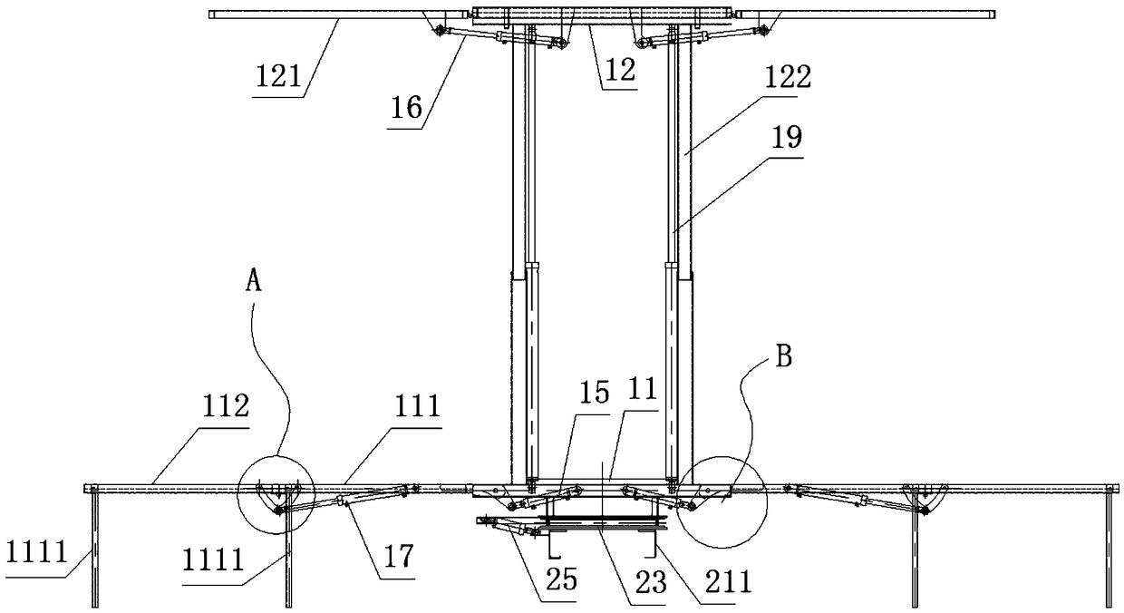
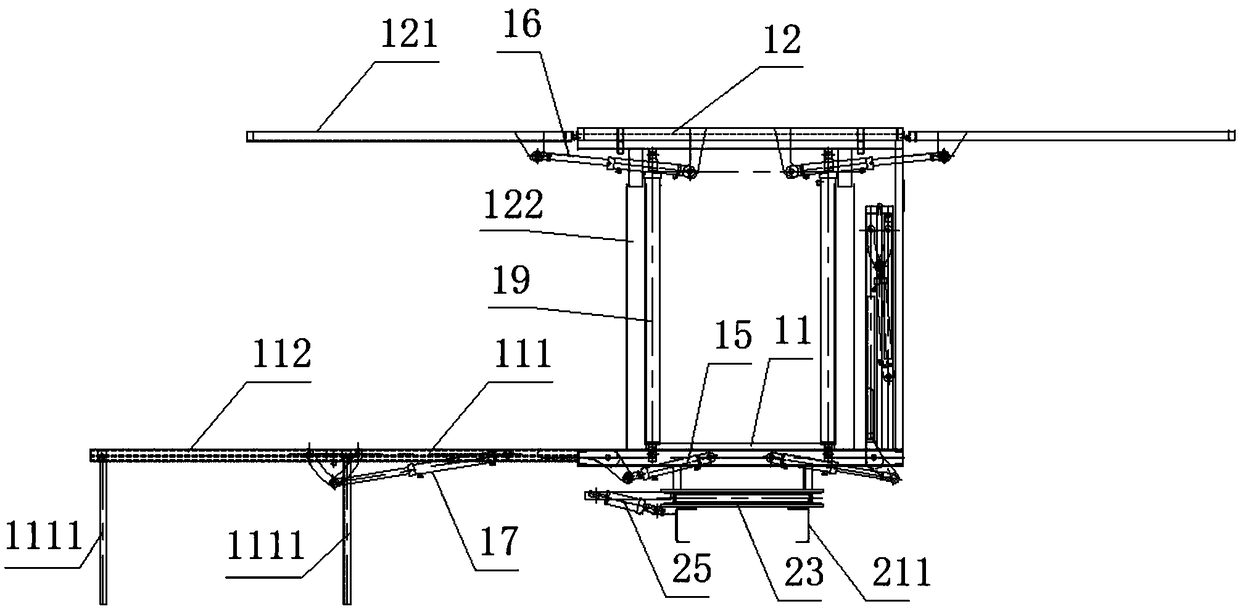
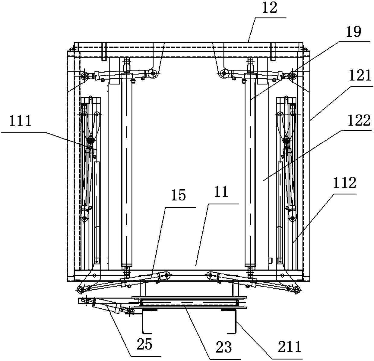
[0045] like figure 1 , figure 2 , image 3 As shown, a single-layer rotary stage vehicle includes a headstock, a main frame 21, and a rotating frame 22, and the headstock drives the main frame 21 to move. The rotating frame 22 is rotatably fixed on the main frame 21 through the turntable bearing 23 and moves longitudinally along the main frame 21 .

[0046] like Figure 15 , Figure 16 , Figure 17 , Figure 18As shown, the main frame 21 includes two parallel longitudinal beams 211 and a cross beam 212 connecting the two longitudinal beams 211 . Because when the compartment rotates, the distance between the center of rotation and the corner of the compartment is greater than the vertical distance between the center of rotation and the front of the car. Therefore, in order to avoid collisions between the corners of the car and the front of the car during the rotation. The present invention is also fixed with two sliders 231 at the bottom of the turntable bearing 23 . ...

Embodiment 2

[0069] Figure 4 , Figure 5 , Figure 6 Shown, a kind of double-deck stage car, can be set to the stage of rotation, also can be designed as non-rotating, present embodiment provides the non-rotating double-deck stage car. That is, on the basis of Embodiment 1, an equipment compartment 10 is added, and the equipment compartment 10 is in the compartment. The specific structure is:

[0070] The two side walls 101 of the equipment compartment 10 are hinged to the top wall 102 respectively, and are respectively driven and unfolded by the third driving mechanism 18 to form a platform coplanar with the top wall 102 of the equipment compartment 10 .

[0071] Such as Figure 12 As shown, LED display screens 103 can also be installed on both sides of the equipment compartment 10 . If it is larger than the side wall of the equipment compartment 10, the display screen 103 can be designed as a main screen 1031 and two side screens 1032. The two side screens 1032 are hinged on both s...


PUM


Abstract

The invention provides a single-layer rotating stage vehicle. A rotating vehicle frame is rotatably arranged on a main vehicle frame and moves in the longitudinal direction of the main vehicle frame. Specifically, bottom plate unfolded wings are hinged to the two sides of a bottom plate, and top plate unfolded wings are hinged to the two sides of a top plate. The stage vehicle further comprises a first driving mechanism and a second driving mechanism, wherein the first driving mechanism drives the bottom plate unfolded wings to be unfolded to be located on the same plane with the bottom plate, or drives the bottom plate unfolded wings to be folded to be used as inner side walls of a compartment; and the second driving mechanisms drives the top plate unfolded wings to be unfolded to be located on the same plane with the top plate, or drives the top plate unfolded wings to be folded to be used as outer side walls of the compartment. The top plate is fixed to the bottom plate through a plurality of guide columns, and a fourth driving mechanism is used for driving the top plate to move up and down. According to the single-layer rotating stage vehicle provided by the invention, a stage is high and can meet the requirements of different programs, and through driving of the driving mechanisms, a semi-automatic folding-unfolding function is achieved; and the requirement of the rotating stage vehicle for sites is lower, and the rotating stage vehicle is higher in adaptability.

Description

technical field [0001] The invention relates to a mobile stage, in particular to a single-layer rotating stage vehicle. Background technique [0002] Performing at the grassroots level by theatrical actors has enriched the cultural life of people in mountainous rural areas and remote areas. However, due to the large workload of moving performance stage and equipment, more manpower and material resources are required, and the grassroots lacks corresponding performance venues, which cannot meet the performance requirements of actors, thus affecting the effect of mobile performances. In order to solve the impact of the stage on the performance, the stage car came into being. In the prior art, the stage car mostly unfolds the left and right side walls to form a stage with the bottom wall of the carriage, and its area is limited, and the types of programs performed are limited to a certain extent. And the height of the stage roof plate in the prior art is determined, and the pr...

Claims


Application Information

Patent Timeline
Patent Type & Authority Patents(China)
IPC IPC(8): B60P3/025
CPCB60P3/0252
Inventor 全秀靖全威王超马杰华
Owner 蒙城县东正汽车有限公司
Why Eureka
Try Eureka